Introduction
Optical Ground Wire (OPGW) is the cable that does double duty on high-voltage transmission lines: it serves as the overhead ground wire for lightning protection while simultaneously carrying optical fibers for high-speed communication between substations. Because OPGW is installed at the top of the tower—replacing or supplementing the traditional bare ground wire—it is exposed to the full mechanical, electrical, and thermal stresses of the transmission system. Proper OPGW selection requires careful analysis of short circuit current capacity, rated tensile strength, DC resistance, and voltage level requirements. This guide provides transmission engineers and utility planners with a comprehensive framework for specifying OPGW cable, from structure type selection through installation planning and common pitfalls to avoid.
For background on how OPGW fits within the broader family of outdoor fiber cables, see our outdoor fiber optic cable types guide. To compare OPGW against ADSS for power line applications, read our ADSS cable selection guide for power lines.
OPGW Structure Types
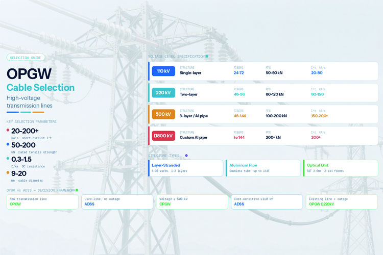
OPGW is fundamentally a composite cable: an optical unit at the center surrounded by one or more layers of metallic wires that provide both mechanical strength and electrical conductivity. The structure type determines fiber capacity, short circuit performance, and mechanical characteristics.
Layer-Stranded Type
The most common OPGW structure is the layer-stranded type. A stainless steel tube containing the optical fibers and filling gel is placed at the center, and layers of aluminum-clad steel wires and aluminum alloy wires are stranded concentrically around it. The aluminum-clad steel wires provide high tensile strength (the steel core) combined with good conductivity (the aluminum cladding), while the aluminum alloy wires add conductivity for fault current distribution.
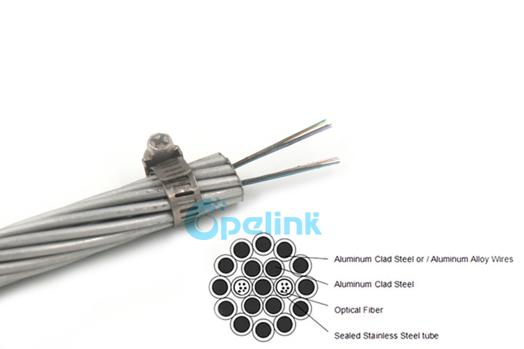 Typical configurations:
- Single-layer: 6–8 wires around the optical unit, diameter 9–12 mm, suitable for 110 kV lines
- Two-layer: 12–18 wires in two layers, diameter 12–16 mm, suitable for 220 kV lines
- Three-layer: 18–30 wires in three layers, diameter 16–20 mm, suitable for 500 kV lines
Layer-Stranded Type with Aluminum Pipe
For applications requiring higher fiber counts or improved short circuit performance, a layer-stranded type with aluminum pipe is used. A seamless aluminum tube replaces or supplements the stainless steel tube, providing a larger optical unit that can accommodate 48 to 144 fibers. The aluminum pipe also contributes to short circuit current capacity by providing additional aluminum cross-sectional area. This structure is preferred for 500 kV and UHV transmission lines where both high fiber count and high fault current capacity are required.
Optical Unit
The optical unit is the heart of the OPGW. It consists of a stainless steel tube (typically 3–6 mm in diameter) containing:
- 2 to 144 optical fibers (typically G.652D single-mode for utility applications)
- Thixotropic gel for water blocking and fiber lubrication
- Optional water-swellable yarns for secondary moisture protection
The stainless steel tube hermetically seals the fibers, protecting them from moisture, hydrogen ingress, and mechanical damage during stranding and installation. The tube is designed to withstand the stranding pressure of the outer wire layers without deformation.
Key Selection Parameters
Selecting OPGW is fundamentally about matching the cable's electrical and mechanical ratings to the transmission system's requirements. Four parameters are critical.
Short Circuit Current Capacity (I²t)
The short circuit current capacity is the most critical OPGW selection parameter. When a fault occurs on the transmission line, the fault current flows through the ground wire (OPGW) back to the source. The OPGW must survive this current without exceeding its temperature limit or damaging the optical fibers.
The short circuit current capacity is expressed as an I²t value (kA²s) and is calculated as:
I²t = (k × S² × ln(T₁ / T₀)) / (ρ × α × t)
Where:
- k = material constant (depends on conductor material)
- S = cross-sectional area of aluminum/aluminum alloy (mm²)
- T₁ = maximum allowable temperature (°K), typically 200°C for OPGW
- T₀ = initial temperature (°K), typically 75°C (operating) or 40°C (ambient)
- ρ = electrical resistivity of the conductor material (Ω·mm²/m)
- α = temperature coefficient of resistance (1/°K)
- t = fault duration (s)
Typical I²t Requirements
| Application |
Typical I²t Range |
Notes |
| Distribution (≤110 kV) |
20–80 kA²s |
Lower fault currents, shorter relay times |
| Transmission (220 kV) |
80–150 kA²s |
Moderate fault currents, standard relay coordination |
| High-voltage transmission (500 kV) |
150–200 kA²s |
High fault currents, critical relay coordination |
| UHV (±800 kV DC) |
200+ kA²s |
Special design, maximum requirements |
The I²t value must be coordinated with the relay protection clearing time (typically 0.5–1.0 seconds for transmission lines). A common mistake is specifying the cable based on normal fault current without accounting for future system expansion that may increase available fault current by 20–40%.
Rated Tensile Strength (RTS)
The RTS of OPGW must match the tower design loads, including wind, ice, and broken conductor cases. OPGW RTS typically ranges from 50 kN to 200 kN:
- 50–80 kN: 110 kV lines, standard tower spacing (200–300 m)
- 80–120 kN: 220 kV lines, longer spans (300–450 m)
- 100–200 kN: 500 kV lines, long spans (450–600+ m), heavy loading districts
The everyday tension should be limited to 15–20% of RTS, with maximum tension under worst-case loading not exceeding 40% of RTS. The OPGW sag must be coordinated with the phase conductor sag to maintain proper electrical clearances—typically the OPGW sag should be slightly less than or equal to the top conductor sag.
DC Resistance
The DC resistance of OPGW affects how fault current distributes between the OPGW and other parallel ground paths (tower grounding, parallel circuits, earth return). Lower resistance means more fault current flows through the OPGW, requiring higher I²t capacity. Typical DC resistance values range from 0.3 to 1.5 Ω/km. In systems with low tower footing resistance, more current flows through the towers and less through the OPGW; in systems with high footing resistance, the OPGW carries more of the fault current.
Diameter
OPGW diameter (typically 10–20 mm) affects wind and ice loading on the tower. A larger diameter increases wind area and ice accumulation, which increases mechanical loading on the tower arm. The diameter must be checked against the tower's ground wire support design loads. In some cases, selecting a compact OPGW design (fewer but larger wires) can reduce diameter while maintaining the required electrical cross-section.
Temperature Rating
OPGW operates over a wide temperature range:
- Continuous operating: −40°C to +80°C (under normal solar and electrical loading)
- Short circuit event: up to +200°C for the duration of the fault (typically ≤1 second)
- Storage and transport: −40°C to +60°C
The optical fibers inside the stainless steel tube are qualified to IEC 60794-1-2 temperature cycling tests. The gel filling compound must remain stable and non-dripping across the full temperature range to maintain fiber protection.
Voltage Level Guidelines
The voltage level of the transmission line drives the selection of OPGW structure, fiber count, RTS, and short circuit capacity. The following guidelines represent typical industry practice:
110 kV Lines
| Parameter |
Typical Range |
| Structure |
Single-layer stranded, stainless steel tube |
| Fiber count |
24–72 fibers |
| RTS |
50–80 kN |
| Diameter |
9–12 mm |
| Short circuit capacity |
20–80 kA²s |
| DC resistance |
0.8–1.5 Ω/km |
At 110 kV, standard OPGW designs are adequate. The fault current levels are moderate, and tower mechanical loads are relatively low. A 48-fiber cable provides ample capacity for current communication needs plus future expansion.
220 kV Lines
| Parameter |
Typical Range |
| Structure |
Two-layer stranded, stainless steel tube |
| Fiber count |
48–96 fibers |
| RTS |
80–120 kN |
| Diameter |
12–16 mm |
| Short circuit capacity |
80–150 kA²s |
| DC resistance |
0.5–1.0 Ω/km |
At 220 kV, the OPGW for 220kV transmission line must have higher short circuit capacity and RTS. Two-layer construction provides the necessary aluminum cross-section for fault current and the mechanical strength for longer spans. Fiber counts of 48–96 are typical, with 96 fibers becoming standard for new construction to support future substation automation and protection redundancy.
500 kV Lines
| Parameter |
Typical Range |
| Structure |
Three-layer or aluminum pipe type |
| Fiber count |
48–144 fibers |
| RTS |
100–200 kN |
| Diameter |
16–20 mm |
| Short circuit capacity |
150–200+ kA²s |
| DC resistance |
0.3–0.6 Ω/km |
At 500 kV, OPGW selection becomes critical. Fault currents are high, spans are long, and the consequences of OPGW failure are severe (loss of both ground wire protection and communication). Three-layer or aluminum pipe structures provide the maximum aluminum cross-section for short circuit capacity and the mechanical strength for long-span, heavy-loading conditions. Detailed system short circuit studies and tower loading analysis are essential.
±800 kV UHV DC Lines
Ultra-high-voltage DC transmission lines require special OPGW designs with maximum mechanical and electrical requirements. The long spans (600–1000+ m), extreme wind and ice loading, and very high fault currents demand customized OPGW with RTS above 200 kN, large-diameter aluminum pipe construction, and fiber counts up to 144. These projects typically involve detailed engineering studies and custom manufacturing.
OPGW Installation Requirements
OPGW installation is more complex than ADSS because it involves the ground wire position at the top of the tower and must be coordinated with the overall transmission line stringing operation.
Installation Timing
OPGW must be installed either:
- During new line construction: OPGW is strung as part of the initial line construction, typically after the phase conductors are installed (or simultaneously on some projects)
- With a planned outage: When replacing an existing bare ground wire with OPGW, the line must be de-energized. This is a key disadvantage compared to ADSS, which can be installed live-line
Tension Stringing Method
OPGW is installed using the tension stringing method to prevent damage to the optical fibers:
- A pilot wire is pulled through the travelers (stringing blocks) installed on each tower
- The OPGW is attached to the pilot wire and pulled through using a bullwheel tensioner that maintains controlled tension
- Tension is kept at 5–15 kN during stringing to keep the cable off the ground and prevent twisting
- The minimum bending radius on the bullwheel must be at least 40 times the cable diameter (typically 30–40 dynamic, 20 static for permanent bends)
- Anti-twisting devices are used to prevent the OPGW from rotating, which could damage the fiber unit
Sag Adjustment
After stringing, the OPGW sag is adjusted to match the design sag-tension curve. The OPGW sag must be coordinated with the phase conductor sag to maintain electrical clearances:
- OPGW sag should be equal to or slightly less than the top conductor sag
- This ensures the OPGW remains above the conductors under all loading conditions, maintaining its lightning shielding angle
- Sag is measured at the span midpoint using a theodolite or total station, and tension is adjusted at the dead-end towers
Joint Boxes and Splicing
- Joint boxes are installed on the tower at designated splice points, typically every 4–8 km depending on fiber attenuation budget and tower access
- Joint boxes must be accessible for maintenance—placed at a reachable height on the tower body, not on the cross-arm
- Splicing is performed after the OPGW is installed and tensioned. Fibers are spliced inside the joint box using fusion splicing, with splice loss typically ≤0.05 dB per splice
- The spliced fibers are organized in splice trays and the joint box is sealed to the environmental rating (typically IP67 or better)
OPGW vs ADSS Comparison for Transmission Lines
The choice between OPGW and ADSS for transmission line communication depends on whether the line is new or existing, the voltage level, and whether an outage can be scheduled.
| Factor |
OPGW |
ADSS |
| Primary function |
Ground wire + fiber communication |
Fiber communication only |
| Installation |
During construction or with outage |
Live-line installation possible |
| Initial cost |
$2.10–3.50/ft |
$0.90–1.60/ft |
| Service life |
40+ years |
25–40 years (AT sheath reaching 40) |
| Voltage suitability |
≥110 kV (designed for transmission) |
≤500 kV (with AT sheath) |
| Short circuit exposure |
Designed to carry fault current |
Must avoid high electric field zones |
| Lightning protection |
Yes (primary function) |
No (no metal, not a target) |
| Maintenance |
Joint boxes on tower, accessible |
Similar, but cable lower on tower |
Decision Framework
- New transmission line → OPGW: Install during construction; dual function provides best long-term value
- Existing line + no outage possible → ADSS: Live-line installation avoids costly outage
- Existing line + outage feasible → OPGW if voltage ≥220 kV; ADSS if voltage ≤110 kV
- Very high voltage (≥500 kV) → OPGW strongly preferred: electric field management for ADSS is extremely difficult at 500 kV
- Cost-sensitive project at ≤110 kV → ADSS: 30–50% lower initial cost than OPGW
For a detailed cost breakdown, see our fiber optic cable cost and price analysis.
Common Selection Mistakes
Avoiding these common errors will help ensure a reliable OPGW installation:
1. Underestimating Short Circuit Current Capacity
The most frequent and consequential mistake is specifying OPGW with insufficient I²t capacity. Engineers sometimes calculate fault current based on current system conditions without accounting for future generation additions, new parallel lines, or system reconfiguration that will increase available fault current. Recommendation: Specify I²t capacity with a minimum 25% margin above the calculated maximum fault current, and verify against the 10-year system expansion plan.
2. Ignoring Future System Expansion
Selecting a fiber count that meets only current needs locks the utility into the selected count for the 40+ year life of the cable. Adding fibers later requires replacing the OPGW—a major project requiring an outage. Recommendation: Specify at least 48 fibers for 110 kV, 96 fibers for 220 kV, and 144 fibers for 500 kV, even if current needs are lower. Dark fiber costs nothing to carry and provides enormous future flexibility.
3. Mismatched RTS with Tower Design
Selecting OPGW with an RTS that does not match the tower's ground wire support design loads can lead to structural issues—either the tower is over-stressed by a heavier OPGW, or the OPGW is under-designed for the tower's span and loading. Recommendation: Obtain the tower design loading data (maximum ground wire tension, wind span, weight span) and verify the OPGW RTS exceeds these with adequate margin (typically 2.5× working tension).
4. Inadequate Corrosion Protection for Coastal Areas
In coastal or industrial pollution environments, the aluminum-clad steel wires can experience galvanic corrosion at the steel-aluminum interface, particularly if the cladding is thin. Recommendation: Specify OPGW with thick aluminum cladding (minimum 8% of wire radius) or solid aluminum-clad steel wires, and consider applying anti-corrosion grease between wire layers for severe environments. Verify the corrosion protection class per IEC 61089 or ASTM B502.
OPGW Selection Checklist
[1] System short circuit current calculated for present and future (10-year) conditions
[2] I²t capacity of selected OPGW exceeds maximum fault current with ≥25% margin
[3] Relay clearing time confirmed and coordinated with I²t calculation
[4] RTS matches or exceeds tower ground wire design loads
[5] DC resistance reviewed for fault current distribution analysis
[6] Diameter checked against tower wind/ice loading capacity
[7] Fiber count specified with future expansion margin (min 48 for 110 kV, 96 for 220 kV, 144 for 500 kV)
[8] Fiber type confirmed (G.652D standard, or G.655 for DWDM if required)
[9] Structure type selected based on voltage and fiber count requirements
[10] Sag-tension curve calculated and coordinated with phase conductor sag
[11] Installation method planned (tension stringing, bullwheel tensioner specified)
[12] Joint box locations planned at accessible towers, spacing within fiber budget
[13] Corrosion protection specified for coastal/industrial environments
[14] Temperature range verified for installation site conditions
Conclusion
OPGW cable selection for high-voltage transmission lines is an engineering decision that balances electrical performance (short circuit current capacity, DC resistance), mechanical performance (RTS, sag-tension coordination), and long-term system planning (fiber count, future expansion). The short circuit current capacity is the single most critical parameter—underestimating it risks catastrophic cable failure during fault events. By following the systematic selection process and checklist in this guide, and avoiding the common mistakes identified, transmission engineers can specify OPGW systems that deliver reliable lightning protection and fiber communication for the 40+ year design life of the transmission line.
Ready to specify OPGW for your transmission line project? OPELINK manufactures a complete range of OPGW cables including layer-stranded and aluminum pipe types, fiber counts from 2 to 144, RTS ratings from 50 kN to 200+ kN, and I²t capacities up to 200+ kA²s. Our engineering team provides system-specific short circuit analysis, sag-tension calculations, and tower loading verification. Contact us for a technical consultation or browse our OPGW cable product catalog to find the right cable for your application.
FAQ
1. What is the most important parameter when selecting OPGW cable?
The short circuit current capacity (I²t) is the most critical parameter. If the OPGW cannot survive the system's maximum fault current for the relay clearing time, the cable will be damaged—potentially destroying the optical fibers and compromising both communication and lightning protection. Always calculate I²t with a margin for future system expansion and coordinate it with the relay protection clearing time.
2. Can OPGW be installed on an energized transmission line?
No. OPGW must be installed during line construction or during a planned outage. This is because OPGW replaces or supplements the ground wire at the top of the tower, which requires working on the tower structure in the high-voltage environment. The tension stringing process also requires travelers and pulling equipment that are not compatible with live-line work. If an outage is not possible, ADSS cable is the alternative for adding communication to an existing line.
3. How many fibers should I specify in an OPGW cable?
For new construction, specify at least 48 fibers for 110 kV lines, 96 fibers for 220 kV lines, and 144 fibers for 500 kV lines, even if current communication needs are lower. OPGW has a 40+ year service life, and adding fibers later requires replacing the entire cable with an outage. Dark (unused) fibers cost essentially nothing to include in the initial installation but provide enormous value for future substation automation, protection redundancy, and third-party leasing.
4. What is the difference between layer-stranded OPGW and aluminum pipe OPGW?
Layer-stranded OPGW has a stainless steel optical unit at the center with metallic wires stranded around it. It is the standard structure for most applications. Aluminum pipe OPGW replaces or supplements the stainless steel tube with a seamless aluminum tube, providing a larger optical unit (more fibers) and additional aluminum cross-section (higher short circuit capacity). Aluminum pipe types are preferred for 500 kV and UHV lines where both high fiber count and high fault current capacity are required.
5. How does OPGW compare to ADSS in cost?
OPGW costs approximately $2.10–3.50 per foot compared to ADSS at $0.90–1.60 per foot, making ADSS 30–50% cheaper in initial cable cost. However, OPGW provides dual functionality (ground wire + fiber) and has a longer service life (40+ years vs 25–40 years), which can make the total cost of ownership comparable or lower for new construction where a ground wire is needed regardless. For existing lines where only communication is being added, ADSS is typically more economical. See our cost analysis for a detailed comparison.
Related articles

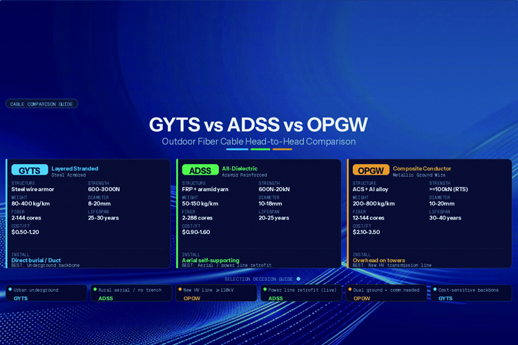 GYTS vs ADSS vs OPGW: Outdoor Fiber Cable Comparison
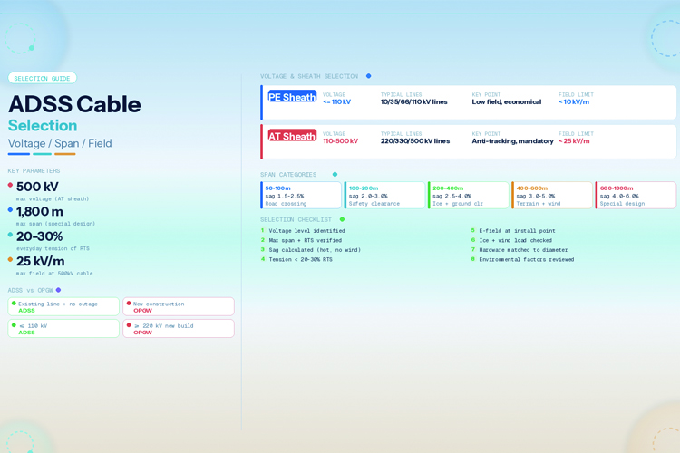 ADSS Cable Selection Guide for Power Lines: Voltage, Span & Environment
 Outdoor Fiber Optic Cable Installation Guide: Aerial, Duct & Direct Burial Methods
 Outdoor Fiber Optic Cable Types: GYTS, ADSS and OPGW Guide


