Introduction
All-Dielectric Self-Supporting (ADSS) cable has become the go-to solution for adding fiber optic communication to existing power lines without requiring a system outage. Because the cable contains no metallic components, it can be installed on energized towers and poles, making it uniquely suited for retrofit projects on live distribution and transmission lines. Proper ADSS cable selection depends on three interrelated factors: the voltage level of the host power line, the span distance between support structures, and the environmental conditions at the installation site. This guide walks electrical engineers and utility planners through every selection parameter—from sheath type and electric field calculation to sag formulas and hardware matching—so you can specify the correct ADSS cable for any power line application.
For a broader overview of outdoor cable types, see our outdoor fiber optic cable types guide. If you are comparing ADSS against other cable families, our GYTS vs ADSS vs OPGW comparison provides a side-by-side breakdown.
ADSS Cable Structure
Understanding the internal construction of ADSS cable is essential for selecting the right variant for your power line. The design is entirely non-metallic, which is what allows it to operate safely in the high-voltage environment of an energized line.
Central Strength Member: FRP
The core of an ADSS cable is a Fiber Reinforced Plastic (FRP) central member. FRP provides bending stiffness and structural support for the fiber bundle without introducing any conductive material. Unlike the steel central member found in some direct-burial cables, FRP is completely dielectric and will not conduct stray currents or lightning-induced voltages.
Loose Tubes with Optical Fibers
Surrounding the FRP center are loose buffer tubes, each containing up to 12 optical fibers. The tubes are slightly larger than the fibers they hold, giving the fibers slack to2 to accommodate thermal expansion and contraction without inducing microbend losses. The tubes are gel-filled with a water-blocking thixotropic compound that prevents moisture ingress along the cable-2 cable length. Tubes are SZ-stranded around the center to equalize bendingG stresses in all bend directions.
Aramid Yarn Strength Member
The tensile load-bearing element in ADSS is aramid yarn (Kevlar or equivalent), applied in one or more layers between the inner core and the outer sheath. Aramid fibers have a tensile strength-to-weight ratio approximately five times that of steel, yet are fully dielectric. The number and lay angle of aramid layers determine the cable's Rated Tensile Strength (RTS), which typically ranges from 2 kN for light-duty distribution cables to 30 kN or more for long-span transmission applications.
Outer Sheath: PE vs AT
The outer sheath is the most voltage-sensitive component and is the primary determinant of where a given ADSS cable can be deployed:
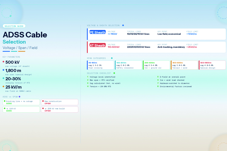
- PE (Polyethylene) sheath: Used for power lines at or below 110 kV. PE offers excellent mechanical toughness, UV resistance, and moisture barrier properties at a moderate cost.
- AT (Anti-Tracking) sheath: Used for power lines above 110 kV up to 500 kV. AT-grade sheath material (typically a modified PE or cross-linked polyethylene compound with enhanced tracking resistance) prevents dry-band arcing and surface tracking that would degrade a standard PE sheath under high electric field stress.
No Metal Components
The defining feature of ADSS is the complete absence of metal. There is no steel armor, no aluminum foil moisture barrier, and no metallic strength member. This makes the cable:
- Immune to electromagnetic interference (EMI) from the host conductors
- Safe to install on energized lines using live-line techniques
- Not a target for direct lightning strikes (though nearby strikes can induce mechanical shock)
Voltage Level Selection
The voltage of the host power line is the single most important factor in ADSS cable selection because it dictates the sheath type and the acceptable installation position on the tower.
PE Sheath: Lines ≤ 110 kV
For standard distribution lines at 10 kV, 35 kV, 66 kV, and 110 kV, a PE-sheathed ADSS cable is the standard choice. The electric field at typical installation points on these towers is low enough that PE will not experience dry-band arcing or tracking degradation. PE sheath cables are less expensive and widely available in configurations from 2 to 144 fibers.
AT Sheath: Lines 110 kV to 500 kV
For transmission lines at 220 kV, 330 kV, and 500 kV, AT-sheathed ADSS cable is mandatory. At these voltage levels, the electric field near the conductor surface is high enough to cause dry-band arcing on a standard PE sheath. Dry-band arcing produces localized hot spots that carbonize the sheath surface, creating conductive tracks that progressively degrade the insulation until the cable fails. AT sheath material resists this carbonization process through additives that suppress surface conductivity under arc conditions.
Why Sheath Type Matters
The failure mechanism is well documented: under high electric field stress, contamination (dust, salt, pollution) on the sheath surface becomes slightly conductive when damp. Leakage current flows through the contamination layer, drying some areas faster than others. The dry bands interrupt the current flow, causing small arcs across the dry areas. On PE, these arcs deposit carbon, which is conductive, accelerating the process. On AT material, the surface resists carbonization, breaking the degradation cycle.
Maximum Voltage: 500 kV
ADSS can be deployed on lines up to 500 kV when AT sheath is used and the installation point on the tower is carefully selected to minimize electric field exposure. Above 500 kV, the field management becomes extremely difficult and OPGW is generally preferred for new construction.
Span Distance & Sag Calculation
Span distance determines the mechanical loading on the cable and the required tensile strength. Every ADSS cable has a maximum recommended span that is a function of its RTS, weight, and allowable sag.
Sag Formula
The sag of a uniformly loaded catenary can be approximated by the parabolic formula for spans up to about 600 meters:
sag = (W × L²) / (8 × T)
Where:
- W = cable weight per meter (N/m)
- L = span length (m)
- T = horizontal tension (N)
Calculation Example
For an ADSS cable weighing 5.0 N/m (approximately 0.51 kg/m) installed on a 200-meter span at a tension of 8,000 N:
sag = (5.0 × 200²) / (8 × 8,000) = (5.0 × 40,000) / 64,000 = 200,000 / 64,000 = 3.125 m
This represents a sag-to-span ratio of 1.56%, which falls within the normal range for this span category.
Span Categories and Typical Sag
| Span Range |
Typical Sag (% of span) |
Key Consideration |
| 50–100 m |
1.5–2.5% |
Road crossing clearance, aesthetic |
| 100–200 m |
2.0–3.0% |
Electrical safety clearance to phase conductors |
| 200–400 m |
2.5–4.0% |
Ground clearance + ice load allowance |
| 400–600 m |
3.0–5.0% |
Terrain clearance + wind load |
| 600–1800 m |
4.0–6.0% |
Special long-span design, reinforced aramid |
Tension Limits
The everyday tension must remain well below the cable's Rated Tensile Strength. Industry practice limits everyday stress to 20–30% of RTS, with maximum allowable tension (under worst-case ice and wind loading) not exceeding 40% of RTS. Exceeding these limits risks aramid yarn creep, fiber strain, and eventual cable failure. For example, a cable with an RTS of 20 kN should be installed at an everyday tension of 4–6 kN.
Maximum Span
With proper cable design (high aramid count, optimized lay angle) and favorable installation conditions, ADSS can achieve spans up to 1,800 meters. However, spans above 600 meters require detailed engineering analysis including wind span, weight span, and weather load cases per IEEE 1222 or IEC 60794-4-20.
Electric Field Considerations
Because ADSS is installed in the high-voltage environment of a power line, the electric field at the installation point must be evaluated and kept below the threshold that the sheath material can tolerate.
Installation at Minimum Field Point
ADSS must be installed at the point of minimum electric field on the tower structure. This is typically:
- Below the lowest conductor on the down-lead or cross-arm, where the field from all phases partially cancels
- Between phases at the tower body, where field cancellation is strongest
- Never above the top conductor (highest field zone)
Electric Field Calculation
A simplified estimate of the electric field at a point near a conductor is:
E = V / (d × ln(2h / r))
Where:
- E = electric field strength (kV/m)
- V = conductor phase voltage (kV)
- d = distance from conductor to installation point (m)
- h = conductor height above ground (m)
- r = conductor radius (m)
This simplified formula gives an order-of-magnitude estimate. For precise values, use a field modeling software (such as CIGRE-recommended 2D or 3D field calculation tools) that accounts for all phase conductors, ground wires, and tower geometry.
Field Limits by Voltage Level
| Voltage Level |
Max Allowable Field at Cable |
Sheath Requirement |
Installation Notes |
| ≤ 110 kV |
< 10 kV/m |
PE acceptable |
Standard installation below lowest conductor |
| 220 kV |
< 15 kV/m |
AT mandatory |
Careful tower point selection, verify with field model |
| 500 kV |
< 25 kV/m |
AT mandatory |
Critical tower point selection, field modeling required |
At 500 kV, the installation point must be verified by detailed electric field modeling. Even with AT sheath, sustained exposure above 25 kV/m will eventually cause tracking failure.
ADSS Hardware Selection
The cable is only one part of the system. Correct hardware selection ensures the cable's mechanical performance over its service life.
Dead-End Assemblies
Used at span terminations (end of a run or at angle towers). Dead-end assemblies grip the cable without crushing the fiber core, typically using preformed helical rods that wrap around the cable and transfer tension to a anchor eye. The assembly must be rated for the cable's maximum tension and matched to the cable diameter.
Suspension Assemblies
Used at intermediate (straight-line) towers where the cable passes through without termination. Suspension assemblies support the cable's weight and provide a minimum bending radius. They typically consist of a helical rod assembly plus a suspension bracket and keeper. The support must allow longitudinal movement to equalize tension across the span.
Downlead Clamps
When the cable drops from the attachment point down the tower to the splice box, downlead clamps secure it at intervals of 1.5–2.0 meters. These clamps must not over-tighten (which would crush the fiber) and should allow thermal movement.
Helical Rods
Helical (armor) rods are applied at all support points to distribute mechanical stress over a longer length of cable, preventing localized crushing and fatigue. Rods must be sized to the exact cable outer diameter—using incorrectly sized rods is a leading cause of premature ADSS failure.
Environmental Factors
Environmental loading affects sag, tension, and long-term cable performance. All factors must be considered in the final selection.
Wind Load
Wind pressure on the cable creates horizontal loading that increases the resultant tension. The wind load per unit length is:
F_wind = 0.5 × ρ_air × Cd × d × V²
Where Cd is the drag coefficient (typically 1.2 for a cylindrical cable), d is cable diameter, and V is wind speed. For design, use the 50-year return period wind speed for the installation region per local loading standards (e.g., ASCE 7, IEC 60826).
Ice Loading
Radial ice accumulation increases the cable's effective weight and diameter. Ice load is typically specified as a radial thickness (e.g., 12.7 mm per NESC Heavy Loading District). Ice increases sag (more weight) but also increases wind area (more wind load). The combined ice-and-wind case is often the governing load condition.
Temperature Variation
Sag changes with temperature. Higher temperatures cause the cable to expand and sag to increase; lower temperatures reduce sag but increase tension. The thermal sag-tension relationship must be calculated across the full temperature range (typically −40°C to +65°C) to ensure clearance is maintained at maximum sag (hot day, no wind) and tension stays within limits at minimum sag (cold day, maximum ice).
UV Resistance
Both PE and AT sheath compounds are UV-stabilized with carbon black or UV absorber additives. UV degradation is not typically a limiting factor for properly formulated sheaths, but cables in high-UV environments (high altitude, tropical sun) should be verified for UV resistance per IEC 60794-2-22.
Lightning
ADSS is not a direct lightning target because it contains no metal. However, a lightning strike to a nearby phase conductor or tower can induce a voltage surge in the cable through capacitive coupling. While the all-dielectric construction prevents current flow, the mechanical shock wave from a nearby strike can cause aramid yarn breakage or sheath damage. In high lightning incidence areas, consider additional mechanical protection at support points.
ADSS vs OPGW Decision for Power Lines
The choice between ADSS and OPGW is one of the most common decisions in power line communication planning. The key decision factors are:
| Scenario |
Recommended Cable |
Rationale |
| Existing line + no outage possible |
ADSS |
Can be installed live-line; OPGW requires outage |
| New line construction or outage feasible |
OPGW |
Dual function (ground wire + fiber), longer life |
| Voltage ≤ 110 kV |
ADSS typically more economical |
Lower cost, PE sheath adequate |
| Voltage ≥ 220 kV + new construction |
OPGW often better |
ADSS electric field management difficult at high voltage |
| Coastal/high pollution area |
OPGW or AT-sheath ADSS |
AT sheath resists tracking; OPGW has no sheath tracking issue |
ADSS Selection Checklist
Use this checklist to ensure all critical parameters have been evaluated before specifying an ADSS cable:
[1] Voltage level of host power line identified (determines PE vs AT sheath)
[2] Maximum span distance measured and cable RTS verified adequate
[3] Sag calculated for hot-day, no-wind condition; ground clearance verified
[4] Tension verified to be within 20–30% of RTS for everyday condition
[5] Electric field at installation point calculated or modeled; within sheath limit
[6] Ice and wind load cases checked per local loading standard
[7] Hardware (dead-end, suspension, downlead) matched to cable diameter
[8] Fiber count and type specified (single-mode OS2 typical for utility)
[9] Environmental factors reviewed (UV, pollution, lightning incidence)
[10] Installation method confirmed (live-line vs de-energized)
[11] Splice box locations planned on towers with adequate access
Conclusion
Selecting the right ADSS cable for a power line application requires a systematic evaluation of voltage level (which determines sheath type), span distance (which determines RTS and sag), and environmental conditions (which affect loading and long-term performance). The all-dielectric construction that makes ADSS installable on live lines is also what makes correct sheath selection critical—PE for ≤110 kV and AT for higher voltages is not a suggestion but a requirement for reliable service. By following the selection process and checklist in this guide, you can specify an ADSS system that will deliver decades of reliable fiber communication on your power infrastructure.
Ready to specify ADSS cable for your power line project? OPELINK manufactures a complete range of ADSS cables with PE and AT sheaths, fiber counts from 2 to 288, and RTS ratings from 2 kN to 30+ kN. Contact our engineering team for site-specific recommendations, sag-tension calculations, and hardware matching. Request a quote or browse our ADSS cable product catalog to get started.
FAQ
1. Can ADSS cable be installed on a live power line without an outage?
Yes. This is one of the primary advantages of ADSS. Because the cable is fully dielectric, it can be installed on energized lines using live-line work techniques (hot-stick, bucket truck with insulation, or helicopter). This avoids the cost and disruption of a planned outage, which is especially valuable on critical transmission circuits that cannot easily be de-energized.
2. What is the maximum voltage for ADSS cable?
ADSS cable can be used on power lines up to 500 kV when equipped with AT (anti-tracking) sheath and installed at a tower position where the electric field is within the sheath's tolerance. Above 500 kV, the electric field management becomes extremely challenging and OPGW is generally the preferred solution.
3. How do I calculate the sag for an ADSS cable span?
Use the parabolic sag formula: sag = (W × L²) / (8 × T), where W is the cable weight per meter in N/m, L is the span length in meters, and T is the horizontal tension in Newtons. For spans over 600 meters, the catenary equation should be used for greater accuracy. Always verify sag at the maximum temperature condition (typically +65°C with no wind) to ensure ground clearance.
4. What is the difference between PE and AT sheath on ADSS cable?
PE (polyethylene) sheath is used on power lines at or below 110 kV where electric field stress is low. AT (anti-tracking) sheath is required above 110 kV where the higher electric field can cause dry-band arcing and surface tracking on standard PE. AT sheath contains additives that resist carbonization under arc conditions, preventing the progressive degradation that would occur with PE. AT sheath costs approximately 15–25% more than PE.
5. What span distance can ADSS cable achieve?
Standard ADSS cables are designed for spans up to 600 meters. With reinforced aramid yarn layers and optimized design, long-span ADSS can achieve spans up to 1,800 meters. The achievable span depends on the cable's RTS, weight, allowable sag, and the wind/ice loading conditions at the site. Always perform a sag-tension analysis for the specific installation conditions.
Related Guides
Outdoor Fiber Optic Cable Types: GYTS, ADSS & OPGW Guide
Outdoor Fiber Optic Cable Installation Guide

 Outdoor Fiber Optic Cable Installation Guide: Aerial, Duct & Direct Burial Methods
 Outdoor Fiber Optic Cable Types: GYTS, ADSS and OPGW Guide
 ADSS Cable for 110kV Power Line: Specifications, Selection & Pricing Guide
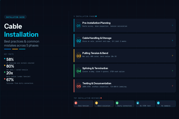 Fiber Cable Installation Best Practices & Common Mistakes


