
English
Welcome to opelink.com
Technical Guide

Outdoor Fiber Optic Cable Installation Guide: Aerial, Duct & Direct Burial Methods

Views : 297
Author : goodvin
Update time : 2026-09-29 14:15:56

Introduction

Proper installation is the single most critical factor determining the long-term reliability of an outdoor fiber optic cable network. Industry field data consistently shows that 68% of fiber optic cable failures originate within the first 100 meters from termination points — splices, connectors, and closures where handling errors, bend-radius violations, and tension abuse are most likely to occur. When installers follow established best practices and manufacturer specifications, early-life failures can be reduced by up to 60%.
This guide covers the three primary outdoor installation methods — aerial (ADSS), duct, and direct burial (GYTS) — with step-by-step procedures, specification tables, sag-tension calculations, and safety checklists. Whether you are planning an ADSS cable installation along power poles, an outdoor fiber optic cable duct installation through underground conduits, or a GYTS direct burial installation in trenching routes, the methods below are written for field engineers and project managers responsible for commissioning fiber backbone infrastructure.
For an overview of the cable types referenced throughout this guide, see our outdoor fiber optic cable types guide (GYTS, ADSS, OPGW).
Outdoor Fiber Optic Cable Installation Guide: Aerial, Duct & Direct Burial Methods

Pre-Installation Planning

Thorough planning before any cable is deployed prevents the majority of installation-related failures. The following four planning phases should be completed for every project.

Site Survey and Route Planning

A comprehensive site survey establishes the physical and environmental conditions along the proposed route:
  1. Route measurement: Walk or drive the entire route; record actual distances (not map estimates). GPS waypoints should be logged every 50 m for direct burial and at every pole for aerial.
  2. Obstacle identification: Note existing utilities (power lines, water mains, gas pipelines), road crossings, waterway crossings, and vegetation that may interfere.
  3. Terrain assessment: Classify soil type for trenching (clay, sandy, rocky, frozen), pole condition for aerial, and duct availability for conduit routes.
  4. Environmental factors: Record temperature ranges, flood risk areas, and wildlife concerns (rodents, termites, birds).
  5. Access verification: Confirm that all route segments are accessible by equipment and personnel.

Cable Selection Verification

Before deployment, verify that the cable on site matches the engineering design:→armored vs non-armored fiber optic cable selection
Parameter Verification Item
Cable type Confirm GYTS for direct burial, ADSS for aerial, or appropriate type per design
Fiber count Match ordered count (e.g., 24, 48, 96, 144) with splice plan
Cable length Measure actual drum length; add 5-10% slack allowance
Attenuation Review factory OTDR test report; verify <=0.36 dB/km at 1310 nm (single-mode)
Tensile rating Confirm rated tensile strength matches installation method requirements
Operating temperature Verify cable temperature range covers local extremes

Permits and Approvals

Secure all regulatory approvals before mobilization:
  1. Right-of-way (ROW) permits from property owners and municipal authorities
  2. Road crossing permits from highway departments (typically requires steel casing)
  3. Railway crossing permits from rail authorities if applicable
  4. Aerial permits: pole attachment agreements with utility pole owners
  5. Environmental clearances for waterway crossings or protected areas
  6. Dig-safe / utility locate services: mandatory before any excavation (call 811 in the US or equivalent local service)

Equipment Checklist

Ensure all equipment is on site, calibrated, and in working order:
Category Equipment
Pulling Cable pulling winch (rated capacity >=2x expected tension), pulling rope (Kevlar or polypropylene), cable rollers, swivel joint
Monitoring Tension monitor (dynamometer), OTDR, optical power meter, VFL (visual fault locator)
Aerial-specific Dead-end assemblies, suspension clamps, down-lead clamps, grounding hardware
Duct-specific Duct cleaning rods, mandrel, cable lubricant, pulling parachute/swab
Direct burial-specific Trenching equipment, sand bedding material, warning tape, marker posts
Splicing Fusion splicer, splice closure, fiber cleaver, strippers, alcohol wipes
Safety Hard hats, high-visibility vests, safety glasses, insulated gloves (for aerial near power lines), traffic cones/barriers

Aerial Installation Method (ADSS Focus)

All-Dielectric Self-Supporting (ADSS) cable is the preferred choice for aerial installation along existing power pole routes because it contains no metallic components and can be installed on energized lines. For a detailed comparison of ADSS against other cable types, see our GYTS vs ADSS vs OPGW cable comparison. →ADSS cable for 110kV power line specifications

Pole Preparation and Hardware Installation

  1. Inspect every pole along the route for structural integrity, rot, and load capacity. Poles must be rated for the additional load of the ADSS cable plus wind and ice loading per IEEE Std 1221.
  2. Install pole hardware at the specified attachment height (typically 1-2 m below the lowest power conductor phase):
  1. Dead-end assemblies at terminal poles and at every angle pole where the route changes direction by more than 5 degrees. These consist of a dead-end clamp, anchor, and down-lead assembly.
  2. Suspension clamps (also called support brackets) at intermediate straight-line poles. These hold the cable with a cushioned grip that allows longitudinal movement.
  1. Verify pole spacing does not exceed the maximum span for the cable's rated tensile strength. ADSS cables typically support spans up to 100-200 m in standard configurations and up to 600 m (and occasionally 1800 m in special long-span designs) with reinforced cables.
  2. Install cable rollers on every pole to guide the cable during pulling and prevent friction damage. Rollers must be positioned at the correct attachment height.

Sag and Tension Calculation

Proper sag-tension calculation prevents both excessive sag (which violates clearance requirements) and excessive tension (which exceeds the cable's rated tensile strength and damages fibers). →ADSS aerial installation guide
The fundamental sag formula is:
Where:
  1. W = cable weight per unit length (N/m)
  2. L = span length (m)
  3. T = horizontal tension component (N)
Typical sag values as a percentage of span length: 
Span Distance Recommended Sag (% of span) Example Sag for 100 m Span
50-100 m 1.5-2.5% 1.5-2.5 m
100-200 m 2.0-3.0% 2.0-3.0 m
200-400 m 2.5-4.0% 2.5-4.0 m
400-600 m 3.0-5.0% 3.0-5.0 m
Example calculation: For an ADSS cable weighing 1.5 N/m spanning 150 m at a tension of 3000 N:

Pulling Process

  1. Set up the pulling winch at one end of the route and the cable drum at the other. Use a swivel joint between the pulling rope and cable to prevent twisting.
  2. Thread the cable through rollers on every pole. Never pull cable directly over pole hardware without rollers.
  3. Begin pulling at a steady speed of 10-30 m/min. Avoid jerking or sudden acceleration.
  4. Monitor tension continuously with a dynamometer. Tension must remain below the cable's rated tensile strength at all times. For ADSS, typical rated tensile is 600-3000 N depending on cable design.
  5. Maintain cable temperature within the rated installation range. Do not install in conditions where ice loading or wind exceeds the cable's design parameters.
  6. Secure the cable at dead-end points first, then adjust sag at intermediate suspension points to match the calculated profile.

Grounding and Bonding Considerations

Although ADSS cable is all-dielectric and does not require grounding for electrical safety, the following still apply:
  1. Metallic hardware (dead-end assemblies, pole brackets) should be bonded to the pole ground if the pole is part of a grounded power line structure.
  2. Down-leads at termination poles must be secured and routed to prevent movement that could stress the cable.
  3. At transitions from aerial to underground, install a transition closure that seals the cable and provides a clean entry to the duct or direct burial section.

Safety: Minimum Approach Distances and Live-Line Work

ADSS can be installed on energized power lines, but strict safety protocols are mandatory:
  1. Minimum approach distances per OSHA 1910.269 depend on system voltage. For 69 kV, the minimum approach distance is 0.64 m; for 230 kV, it is 2.13 m. Always consult the current standard for your voltage class.
  2. Live-line installation requires dedicated live-line-trained crews, insulated tools, and a documented job briefing.
  3. Induced voltage on the cable from parallel power conductors can be significant on long spans; measure and mitigate as needed.
  4. All personnel must wear insulated rubber gloves rated for the system voltage, and use insulated blankets and covers on adjacent energized conductors.
For detailed guidance on selecting ADSS cable for power line installations, see our ADSS cable selection guide for power lines.

Duct Installation Method

Underground duct installation protects fiber cable from weather, vegetation, and accidental damage, making it the most durable long-term deployment method.

Duct Preparation and Cleaning

  1. Inspect the duct (HDPE, PVC, or multi-duct bank) for integrity, continuous inner bore, and correct inner diameter. The duct inner diameter should be at least 1.5x the cable outer diameter.
  2. Clean the duct using a mandrel test: pull a rigid mandrel (approximately 85% of duct inner diameter) through the full length to confirm the bore is clear of obstructions, debris, and collapsed sections.
  3. Install a pulling rope through the duct if one is not already present. Use a parachute or swab pushed through with compressed air, or fish tape for shorter runs.
  4. Apply cable lubricant (polywater or equivalent) to the pulling rope and inside the duct entrance to reduce friction coefficient (target friction coefficient <=0.2).

Pulling Cable Through Duct

  1. Attach the pulling rope to the cable using a Kellums grip (Chinese finger trap) or a pulling eye pre-installed on the cable. Use a swivel joint between the rope and grip to prevent cable rotation.
  2. Position the cable drum on a sturdy jack stand with braking capability. The drum must rotate freely and be braked to maintain back-tension and prevent overrun.
  3. Begin pulling at 10-20 m/min. Apply lubricant continuously at the duct entrance during the pull.
  4. Monitor pulling tension with an in-line dynamometer. Keep tension below 80% of the cable's rated tensile strength to provide a safety margin for friction spikes at bends.

Bend Radius Compliance

Condition Minimum Bend Radius
During installation (dynamic) 20 x cable diameter
Long-term installed (static) 10 x cable diameter
Violating bend radius is one of the most common causes of microbend-induced attenuation. At duct bends and manhole transitions, use cable rollers or radius-limiting sheaves to guide the cable smoothly.

Manhole and Handhole Procedures

  1. Manholes serve as pulling points, splice locations, and cable routing nodes. Install cable rollers at manhole entrances and exits to minimize friction.
  2. Intermediate assist pulling: For routes exceeding 500-1000 m, use an intermediate capstan winch in a manhole to assist the pull. Never exceed the maximum pulling distance in a single pull -- friction accumulates exponentially with distance and bends.
  3. Cable slack: Leave 3-5 m of slack in each manhole for future splicing and re-routing. Coil slack neatly on the manhole wall using cable brackets.
  4. Splice closures: Install weatherproof splice closures (IP68 rated) on the manhole wall. Route cable entries through sealed glands.

Direct Burial Installation Method (GYTS Focus)

Direct burial is the most common method for rural and long-haul fiber routes where duct infrastructure is not available. GYTS cable -- with its steel wire armor and corrugated steel tape -- is purpose-built for this application. For a comprehensive guide focused specifically on GYTS, see our GYTS cable direct burial and duct installation guide.

Trenching

  1. Excavate the trench to the specified depth and width:
Location Trench Depth Trench Width
General terrain 0.8-1.2 m 0.3-0.4 m
Road crossing 1.2-1.5 m 0.3-0.4 m (cased)
Agricultural land 1.0-1.2 m 0.3-0.4 m
River crossing 1.0 m below riverbed As required
  1. Remove sharp rocks and debris from the trench bottom. The trench floor must be smooth and free of objects that could damage the cable armor.

Sand Bedding and Warning Tape

  1. Lay a 10 cm sand bedding layer at the bottom of the trench. Sand provides a uniform, cushioned surface that distributes load and prevents point loading on the cable.
  2. Compact the sand bedding lightly to provide a stable base.

Cable Laying

  1. Deploy the cable manually or mechanically along the trench:
  1. Manual laying: Carry the cable drum along the trench and unroll by hand. Suitable for short distances and delicate terrain.
  2. Mechanical laying: Use a cable plow or tractor-mounted dispenser for long distances. Maintain a steady speed of 20-50 m/min.
  1. Maintain 1-2% slack along the route to accommodate thermal expansion and contraction and to provide spare cable for future repairs.
  2. Avoid sharp bends: Maintain the minimum bend radius (20x diameter during laying). Use sand bags to hold the cable in position at direction changes.

Backfilling and Compaction

  1. First backfill layer: Place 30 cm of fine sand or sieved soil over the cable. Do not use original excavated material if it contains rocks larger than 10 mm.
  2. Install warning tape: Lay a yellow warning tape marked "CAUTION: FIBER OPTIC CABLE BELOW" approximately 30 cm above the cable (midway in the backfill). This provides advance warning to future excavators.
  3. Final backfill: Fill the remaining trench with excavated material, compacting in 15-20 cm layers. Use a tamper or plate compactor, but avoid direct compaction over the cable zone until at least 30 cm of cover is in place.

Marking and Documentation

  1. Install marker posts at intervals of 200-500 m, at all road crossings, direction changes, and splice points. Posts should be yellow with black lettering: "FIBER OPTIC CABLE -- [Owner Name] -- [Phone Number]".
  2. Record GPS coordinates of all markers, splice points, and route changes. Create as-built drawings showing the exact buried route, depths, and splice locations.

Rodent Protection Considerations

In areas with high rodent activity (gophers, rats, squirrels), consider additional protection:
  1. Thicker armor: Specify GYTS with heavier corrugated steel tape (0.15 mm or thicker).
  2. Chemical treatment: Apply rodent-repellent chemical barriers around the cable in the trench.
  3. Concrete encasement: In severe cases, encase the cable in a thin concrete shell at vulnerable sections.
  4. Metallic tape overlap: Ensure the corrugated steel tape has sufficient overlap (>=5 mm) to prevent rodent penetration at the seam.

Termination and Splicing

Fusion Splicing Best Practices

  1. Prepare a clean splicing environment: Use a splice trailer or tent with temperature and humidity control. Dust-free conditions are essential for low-loss splices.
  2. Strip the cable: Remove the PE sheath, steel armor, and loose tube to expose individual fibers. Use proper stripping tools -- never nick the fiber coating.
  3. Cleave each fiber at 90 degrees +/-1 degree using a precision cleaver. A poor cleave angle is the leading cause of high splice loss.
  4. Fuse the fibers using an automated fusion splicer. Target splice loss: <=0.05 dB per splice (typical average 0.02-0.03 dB).
  5. Protect the splice with a heat-shrink splice protector. Verify the protector is fully seated and heated evenly.

Optical Loss Budget Management

Calculate the total link loss and verify it falls within the system budget:
Loss Element Typical Value
Fusion splice 0.05 dB per splice
Connector (UPC) 0.35 dB per connector pair
Connector (APC) 0.25 dB per connector pair
Cable attenuation (1310 nm) 0.36 dB/km
Cable attenuation (1550 nm) 0.22 dB/km
Margin 3.0 dB (recommended)
Example: A 10 km link at 1310 nm with 4 splices and 2 connector pairs (UPC):

Connector Selection and Installation

  1. UPC (Ultra Physical Contact) connectors for standard single-mode links. Return loss >=50 dB.
  2. APC (Angled Physical Contact) connectors for analog or DWDM systems where reflectance is critical. Return loss >=60 dB. APC connectors are color-coded green.
  3. Hybrid mating: Never mate UPC and APC connectors -- this causes an air gap and catastrophic loss. Use hybrid adapters only when explicitly required.

Testing: OTDR, Insertion Loss, and Reflectance →how to read fiber optic cable specifications

  1. OTDR trace: Test from both ends of the link. Verify: total attenuation matches calculated budget, no anomalous loss events (gainers, high-loss points), splice losses within budget, and no reflective events at non-connector locations.
  2. Insertion loss: Measure end-to-end loss with a stabilized light source and power meter. Compare with OTDR results -- they should agree within 0.5 dB.
  3. Reflectance: Measure ORL (optical return loss) at each connector. Minimum acceptable ORL: 32 dB for UPC, 45 dB for APC. 

Common Installation Mistakes and How to Avoid Them

Mistake Consequence Prevention
Excessive pulling tension Fiber strain, attenuation increase, fiber break Monitor tension with dynamometer; keep below 80% of rated tensile
Violating bend radius Microbend loss, cracked fiber, localized attenuation Use radius-limiting rollers; maintain 20xD during install, 10xD static
Inadequate cable preparation Contaminated splice, high splice loss Strip and clean in controlled environment; use alcohol wipes
Poor splice environment Dust contamination, humidity-related failures Use splice trailer with humidity <60% and temperature 15-30C
Improper cable lubrication High friction, tension spikes, jacket damage Apply lubricant continuously; use correct type (not soap or oil)
Insufficient slack at closures Future maintenance requires re-pulling entire section Leave 3-5 m slack at every manhole and splice point
Ignoring thermal expansion Cable strain in temperature extremes Maintain 1-2% slack for direct burial; design sag for aerial

Conclusion

Proper outdoor fiber optic cable installation -- whether aerial, duct, or direct burial -- is the foundation of a reliable communication network. By following the procedures, specifications, and safety protocols outlined in this guide, installers can dramatically reduce the 68% failure rate associated with the first 100 meters from termination points and achieve the 60% reduction in early failures that disciplined installation practices deliver.
Key takeaways:
  1. Plan thoroughly before any cable is deployed -- site survey, cable verification, permits, and equipment readiness.
  2. Monitor tension continuously and never exceed 80% of rated tensile strength during pulling.
  3. Respect bend radius limits -- 20x diameter during installation, 10x diameter static.
  4. Document everything -- GPS coordinates, as-built drawings, splice records, and OTDR traces.

OPELINK manufactures a full range of outdoor fiber optic cables including GYTS for direct burial, ADSS for aerial installation, and OPGW for power line integration. All cables ship with factory OTDR test reports and complete technical datasheets. For a cost analysis comparing different cable types and installation methods, see our fiber optic cable cost and price analysis.
Ready to specify the right cable for your installation project? Contact OPELINK for cable selection assistance, installation consultation, and custom cable design services. Our engineers will help you match the exact cable type, fiber count, and tensile rating to your route conditions and performance requirements.
Installation Safety Checklist

Before and during installation, verify the following:
[1] All personnel have appropriate safety training and PPE (hard hats, safety glasses, high-visibility vests, steel-toe boots)
[2] Traffic control plan implemented for road crossings (cones, barriers, flaggers)
[3] Utility locate completed before any excavation (gas, water, electric, telecom)
[4] Trench shoring installed for trenches deeper than 1.5 m or in unstable soil (per OSHA 1926 Subpart P)
[5] Cable drum inspected for damage; drum lifting uses correct equipment (never lift by flange bolts)
[6] Pulling equipment rated capacity verified (>=2x expected pulling tension)
[7] Tension monitoring device calibrated and in-line during all pulling operations
[8] For aerial work near power lines: minimum approach distances verified, insulated tools and gloves on site, live-line work permit signed if applicable
[9] Weather conditions within safe limits (no installation during lightning, high winds >40 km/h, or extreme temperatures outside cable rating)
[10] Emergency procedures communicated to all crew members; first aid kit and communication devices on site
[11] As-built documentation started during installation (GPS waypoints, splice locations, depth measurements)
 

Frequently Asked Questions

What is the maximum pulling tension for outdoor fiber optic cable?

The maximum pulling tension depends on the cable type and design. For standard GYTS cable, the rated short-term tensile strength is 600 N (standard) up to 3000 N (reinforced). During installation, you should keep pulling tension below 80% of the rated value -- so 480 N for a standard 600 N GYTS. Always consult the manufacturer's datasheet for the specific cable being installed and monitor tension with a calibrated dynamometer throughout the pull.

What is the minimum bend radius for fiber optic cable during installation?

During installation (dynamic loading), the minimum bend radius is 20 times the cable diameter. After installation is complete and the cable is in its permanent position (static loading), the minimum bend radius reduces to 10 times the cable diameter. Exceeding these limits causes microbending losses and can permanently damage the glass fibers inside the loose tubes -- even if the outer jacket appears undamaged.

Can ADSS cable be installed on energized power lines?

Yes. ADSS (All-Dielectric Self-Supporting) cable is specifically designed for installation on energized power lines because it contains no metallic conductive elements. However, live-line installation requires specially trained crews, insulated tools and gloves rated for the system voltage, and strict adherence to minimum approach distances per OSHA 1910.269. Induced voltage from parallel conductors must also be assessed and mitigated on long spans. For guidance on selecting the right ADSS cable for your power line application, see our ADSS cable selection guide.

How deep should a direct burial fiber optic cable be buried?

The standard burial depth for direct burial fiber optic cable is 0.8-1.2 m for general terrain and 1.2-1.5 m for road crossings where the cable passes beneath a roadway. In agricultural land, 1.0-1.2 m is typical to accommodate deep plowing. In areas with frozen ground, the cable should be buried below the local frost line. Always install a yellow warning tape approximately 30 cm above the cable and marker posts every 200-500 m.

How do I calculate the sag for an aerial fiber optic cable installation?

Use the formula sag = (W x L^2) / (8 x T), where W is the cable weight per meter (N/m), L is the span length (m), and T is the horizontal tension (N). The resulting sag should typically be 1.5-5% of the span length depending on span distance. Verify that the calculated tension does not exceed the cable's rated tensile strength and that the sag provides adequate ground clearance under maximum loading conditions (wind, ice).
 

Related Guides

Outdoor Fiber Optic Cable Types: GYTS, ADSS and OPGW Guide
ADSS Cable for 110kV Power Line: Specifications, Selection & Pricing Guide
Fiber Cable Installation Best Practices & Common Mistakes
How to Read Fiber Optic Cable Specifications: Complete Guide
Armored vs Non-Armored Fiber Cable

Related News
Read More >>
Outdoor Fiber Optic Cable Types: GYTS, ADSS and OPGW Guide Outdoor Fiber Optic Cable Types: GYTS, ADSS and OPGW Guide
Sep .22.2026
Compare GYTS, ADSS & OPGW outdoor fiber cables: structure, installation, cost & applications. Find the right cable for your network project.
ADSS Cable for 110kV Power Line: Specifications, Selection & Pricing Guide ADSS Cable for 110kV Power Line: Specifications, Selection & Pricing Guide
Sep .15.2026
Complete guide to ADSS cable for 110kV power lines: AT type requirements, specifications, span calculations, 2026 price reference, RFQ checklist, and common mistakes to avoid.
Fiber Cable Installation Best Practices & Common Mistakes Fiber Cable Installation Best Practices & Common Mistakes
Sep .08.2026
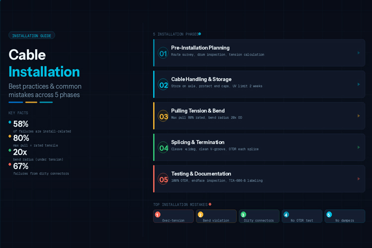
Complete fiber optic cable installation guide: pre-installation planning, pulling tension limits, bend radius compliance, fusion splicing, OTDR testing, connector contamination prevention. Includes top 10 mistakes ranked by failure impact.
How to Read Fiber Optic Cable Specifications: Complete Guide How to Read Fiber Optic Cable Specifications: Complete Guide
Sep .01.2026
Master fiber optic cable specification reading: decode GYTS/GYTA codes, verify G.652.D fiber specs, interpret tensile/crush ratings, read OTDR traces, and check compliance certifications. Includes a 12-point acceptance checklist.