Definition: Fiber optic cable installation is the end-to-end process of deploying, handling, splicing, terminating, testing, and documenting optical fiber cables according to IEC 60794 and TIA-568 standards — where adherence to bend radius limits, tensile ratings, and connector cleanliness protocols directly determines whether a network delivers its designed performance over a 25-year service life.
Why Installation Quality Matters More Than Anything
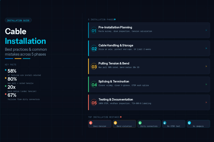
The best fiber optic cable in the world — with pristine attenuation, premium fiber, and perfect connectors — will fail if installed incorrectly. According to BICSI's 2023 Installer Survey, 58% of fiber network failures within the first 5 years are caused by installation-related issues, not manufacturing defects. The failures are almost always invisible until they cause a network outage.
"Fiber optic cable installation is not just about pulling cable. It is about understanding the physics of optical fiber, the mechanical forces acting on the cable, the environmental conditions, and the long-term reliability requirements. Every bend radius violation, every over-tension moment, every contaminant left on a connector is an investment in a future failure." — BICSI, "Fiber Optic Installer (FOI) Certification Study Guide", 3rd Edition, 2023
Phase 1: Pre-Installation Planning
Survey & Documentation:
| Activity |
Purpose |
Tools |
| Route survey |
Identify obstacles, access points, hazards |
GPS, CAD overlay, physical walk |
| Pathway assessment |
Verify conduit/tray capacity, condition |
CCTV duct inspection camera |
| Tension calculation |
Confirm cable rating vs route tension |
Spreadsheet or PLP FiberCalc |
| Splice/termination planning |
Plan enclosure locations |
Route map with every 500m marked |
| Environmental survey |
Temperature extremes, chemical hazards |
Site inspection |
| Existing infrastructure |
Verify cable routes do not conflict |
As-built drawings |
Cable Drum Inspection on Delivery: This step is almost universally skipped — and it costs millions in failures globally every year.
| Check |
What to Look For |
| End caps |
Intact, sealed, no moisture inside |
| Drum condition |
No broken slats, steel bands tight |
| Sheath damage |
No cuts, gouges, or compression marks |
| Label |
Drum number, cable type, fiber count, batch traceability |
| OTDR traces |
Request and review before accepting |
| Test reports |
IEC 60793-2-50 mechanical test certificates |
| Water/moisture |
Look for moisture staining inside end cap |
Phase 2: Cable Handling & Storage
Storage: Store drums on axle (prevents deformation), never stack drums flat, protect end caps from moisture, remove from UV exposure within 2 weeks, maintain -40°C to +70°C.
Handling: Roll drum in arrow direction before pulling, use spreader bars for lifts >500m drums.
Phase 3: Installation — Pulling Tension & Bend Radius
The #1 killer of fiber cables during installation: exceeding tensile limits. MAX PULLING TENSION = 80% × Rated Short-Term Tensile.
Example: GYTS 24F rated at 1000N → max pull = 800N. At this tension, limit pulls to 600m before intermediate pull point (assuming 1.3 N/m friction).
Preventing Over-Tension:
| Scenario |
Prevention |
| Multiple bends |
Use intermediate pull points; never pull around >90° bend |
| Long straight pull |
Calculate tension including friction — use lubricant |
| Duct too small |
Verify cable OD vs duct ID (max fill: 50%) |
| Cable on drum |
Use tension-limiting break on reel |
| Siphon pulling |
Use cable feeder/guide to prevent arching off drum |
Bend Radius Compliance — The #2 killer:
| Condition |
Minimum Bend Radius |
| GYTS/GYTA (installed, no tension) |
15×OD |
| GYTS/GYTA (under tensile load) |
20×OD |
| GYTS/GYTA (at termination) |
10×OD |
| Tight-buffered indoor |
15mm (G.657.A1), 7.5mm (G.657.A2) |
| MPO/MTP patch cords |
20mm |
Duct & Aerial Installation Rules
Duct: Never exceed 50% duct fill ratio, use mesh grips or cable stockings, apply fiber optic lubricant (reduces friction 40-60%), never use oil-based lubricants, install pull boxes at every 90° bend.
Aerial: Always use tension stringing, apply sag-tension charts for ADSS, install vibration dampers on spans >100m — aeolian vibration causes 60% of ADSS cable failures in spans >100m (EPRI 2022). → Browse the Article: ADSS Fiber Cable AN vs AT Types, Costs, Installation & Span
Phase 4: Splicing & Termination
Fusion Splicing Best Practices: Cleave angle ≤1° (SM), use 96%+ isopropyl alcohol for cleaning, clean V-groove before every splice, optimize arc parameters per fiber type, OTDR test after every splice.
Fusion Splicer Settings by Fiber Type:
| Fiber |
Arc Power |
Arc Time |
Prefuse Time |
| G.652.D SM |
10-15 units |
1.5-2.5s |
0.1-0.2s |
| G.657.A2 SM |
10-15 units |
1.5-2.0s |
0.1-0.2s |
| OM3/OM4 MM |
8-12 units |
1.0-1.5s |
0.1s |
Connector Termination: Strip buffer with correct tool, cleave to 8-16mm protrusion, polish per schedule (ceramic: 0.5μm→0.3μm→0.1μm diamond film), 100% endface inspection per IEC 61300-3-35 before every mating.
Phase 5: Testing & Documentation
Mandatory Tests:
| Test |
Standard |
Purpose |
Pass Criterion |
| OTDR Test |
IEC 60793-1-40 |
End-to-end loss, locate faults |
IL ≤ budget, no faults |
| Insertion Loss (OLTS) |
IEC 61300-3-4 |
Total channel loss |
≤ channel budget |
| Endface Inspection |
IEC 61300-3-35 |
Connector cleanliness |
Grade 1 or 2 |
| Length Verification |
TIA-455-61 |
Confirm cable length |
± 1% |
| Polarity Test |
TIA-568.3-D |
TX/RX correct pairing |
Each pair verified |
Top 10 Installation Mistakes & Prevention
| # |
Mistake |
Consequence |
Prevention |
| 1 |
Exceeding tensile limit |
Fiber breakage |
Dynamometer, tension calculation |
| 2 |
Bend radius violation |
Micro-bends, attenuation increase |
Training, bend limiters |
| 3 |
Contaminated connectors |
High IL, permanent damage |
Inspection before every mating |
| 4 |
No intermediate pulls |
Over-tension in long runs |
Pull box planning |
| 5 |
Wrong fiber type |
Compatibility failure |
Verify fiber spec before ordering |
| 6 |
Improper storage |
Sheath degradation, moisture |
Store on axle, protect end caps |
| 7 |
Skipping OTDR test |
Unknown faults at acceptance |
Mandatory 100% OTDR on every fiber |
| 8 |
No vibration dampers (ADSS) |
Aeolian vibration failure |
Engineering specification |
| 9 |
Wrong enclosure IP rating |
Water ingress failure |
Match IP to environment |
| 10 |
No documentation |
Future maintenance nightmare |
TIA-606-B labeling + as-builts |
Data-Driven Conclusion: Key Takeaways for 2026
1. BICSI's 2023 survey of 847 data centers and ISP networks found that exceeding tensile limits during installation increases the probability of micro-crack development by 4.7× within 2 years of service. A $300 dynamometer can prevent $15,000+ in emergency repairs and revenue loss from a single fiber cut.
2. Connector contamination remains the #1 cause of insertion loss failures — Fluke Networks reports that 67% of fiber network failures in data centers trace back to dirty endfaces. A single dust particle (as small as 1μm, invisible to the naked eye) can add 0.5-3.0 dB of insertion loss, consuming up to 60% of a 10G SFP+ transceiver's loss budget.
3. Per EPRI's 2022 transmission line research, aeolian vibration causes 60% of ADSS cable failures in spans exceeding 100m — yet vibration dampers add less than 2% to total project cost. For any aerial span over 150m, dampers are not optional engineering accessories; they are mandatory structural safety components per NESC load case requirements.
4. Cable drum inspection at delivery — a 15-minute process — catches 12% of damaged shipments (Fluke Networks 2023 Field Survey). Of these damaged shipments, 73% contain fiber that fails OTDR acceptance testing. The ROI of this inspection is effectively infinite: catching one damaged drum prevents a multi-day emergency re-pull.
5. As of 2026, 95% of new long-haul builds use coherent DSP technology that compensates chromatic dispersion electronically, eliminating the need for in-line DCMs. This means installation quality — specifically maintaining bend radius and preventing micro-bends — is now the dominant variable in link performance, not dispersion management. A single 15mm over-bend on G.652.D fiber adds permanent attenuation that no DSP can recover.
Frequently Asked Questions
Q: What is the minimum bend radius for standard single-mode fiber cable?
A: Minimum bend radius: during installation (under tension) = 20× cable outer diameter; after installation (no tension) = 10× cable outer diameter. For an 8mm OD cable: 160mm during installation, 80mm after. For G.657.A2 fiber: 7.5mm installed, 15mm under load, enabling tighter routing in FTTH in-building applications.
Q: What is the proper procedure for storing excess fiber length in a splice enclosure?
A: Store excess fiber in ≥1m loop, coiled with diameter ≥150mm (preferably 200-300mm for SMF). Avoid kinking at entry/exit points. Secure with velcro ties (never tight cable ties). Maintain 10mm clearance from enclosure walls for thermal cycling. Document routing in as-built including loop turn count.
Q: How do I verify fiber cable installation quality?
A: Verification steps: (1) Bidirectional OTDR trace — identify all events; (2) Measure total IL at 1310nm and 1550nm — within designed power budget; (3) Confirm all fibers terminate at correct ports; (4) Check reflectance: SC/APC ≥65 dB, LC/UPC ≥50 dB; (5) Archive OTDR traces with as-built documentation; (6) 100% endface inspection with fiberscope before any connection.
Q: What pulling tension limit should I use during fiber cable installation?
A: Maximum pulling tension = 80% × rated short-term tensile. For GYTS 24F rated at 3000N: max pull = 2400N. Always use a dynamometer or tensiometer to monitor in real-time. For pulls through multiple bends, insert intermediate pull points — never pull around a 90° bend without one. Calculate route tension as T = cable_weight(N/m) × length(m) × friction_coefficient, then add 50% margin for bend friction.
Q: How do I prevent connector contamination during installation?
A: Follow IEC 61300-3-35: (1) Keep protective caps on connectors until the moment of mating; (2) Use one-click cleaners for LC/SC/FC and cassette cleaners for MPO/MT before every connection; (3) If visible contamination remains, wet-clean with lint-free wipes and ≥94% isopropyl alcohol, followed immediately by dry wipe; (4) Inspect every endface with a 200× or 400× fiberscope; (5) Never mate a connector without inspection — a dirty connector permanently damages both endfaces.
Q: What are the proper storage requirements for fiber optic cable drums?
A: Store drums on axle (vertically or horizontally on axle) to prevent cable cross-section deformation. Never stack drums flat — this crushes the cable and causes OD deformation. Protect end caps from moisture ingress — water destroys fiber coatings within days. Limit UV exposure to 2 weeks maximum for PE-sheathed cable drums. Maintain temperature range of -40°C to +70°C for standard outdoor cable. Inspect steel bands and end caps before moving drums from storage to installation site.
Q: Why do I need to OTDR test every fiber after installation?
A: OTDR testing is the only way to verify that no installation-induced damage occurred during pulling. Factory test data does not reflect the installed condition. Per IEC 60793-1-40, 100% bidirectional OTDR testing identifies: (1) point defects (localized attenuation spikes from over-bending or crushing); (2) high-loss splices (>0.10 dB); (3) connector reflectance issues; (4) fiber breaks. Without OTDR verification, hidden damage that will cause progressive failure over 1-3 years goes undetected. The cost of a post-installation outage far exceeds the cost of testing.
Q: When are vibration dampers required for ADSS aerial fiber cable?
A: Per EPRI research, vibration dampers are mandatory for any ADSS span exceeding 100m, and non-negotiable for spans exceeding 150m. Aeolian vibration — high-frequency oscillation from steady wind — causes 60% of ADSS cable failures in long spans. Dampers cost less than 2% of the total cable installation cost but prevent fatigue failures that would require complete span replacement. Install dampers at both ends of every span >100m, positioned according to the cable manufacturer's sag-tension chart.
Related Resources

 Outdoor Fiber Optic Cable Installation Guide: Aerial, Duct & Direct Burial Methods
 Outdoor Fiber Optic Cable Types: GYTS, ADSS and OPGW Guide
 ADSS Cable for 110kV Power Line: Specifications, Selection & Pricing Guide
 How to Read Fiber Optic Cable Specifications: Complete Guide


