Key Takeaways
1. The global ADSS cable market reached $1.12 billion in 2025 and is projected to hit $1.97 billion by 2032 (CAGR 8.42%), driven by smart grid modernization and rural FTTH expansion.
2. ADSS now represents 18% of all aerial fiber deployments globally, with annual demand exceeding 200,000 km (EJL Wireless Research 2023).
3. AN Type (≤35kV) vs AT Type (35kV–500kV) — jacket material selection per IEEE 1222 is the #1 factor determining cable lifespan on high-voltage lines. Standard PE jackets fail within months on EHV lines.
4. EPRI field data: 94% of ADSS failures occur at spans exceeding 90% of rated span; always specify a minimum 15% safety margin. Vibration dampers are mandatory for spans ≥150m.
5. Asia-Pacific commands 42.9% of global ADSS spend ($319.8M in 2025), led by China and India's power-grid fiberization programs. North America follows with steady growth fueled by federal rural broadband funding.
Introduction
The global all-dielectric self-supporting (ADSS) fiber cable market reached a valuation of $1.12 billion in 2025, with ADSS now representing 18% of all aerial fiber deployments worldwide — an annual demand exceeding 200,000 kilometers. This growth trajectory, projected to accelerate at an 8.42% CAGR toward $1.97 billion by 2032, reflects a fundamental shift in how utilities and telecom providers approach aerial fiber deployment. Rather than building new infrastructure from scratch, network planners are increasingly leveraging existing power line corridors — an approach that ADSS cable is uniquely engineered to support.
This complete guide provides engineering and procurement teams in the power and telecommunications sectors with a comprehensive reference for ADSS cable selection, span engineering design, and installation best practices. From voltage classification (AN vs. AT) and sag-tension calculations to cost comparisons and application scenarios, every section is designed to support informed decision-making in real-world deployment contexts.
A critical economic advantage merits attention upfront: ADSS cable costs $3,000–$8,000 per kilometer, compared to $15,000–$30,000 per kilometer for OPGW (Optical Ground Wire). When make-ready work is factored in, ADSS installations deliver 15–20% lower total project costs than messenger-wire alternatives (Fiber Broadband Association, 2026). For utilities and broadband operators seeking to maximize coverage per dollar deployed, this cost differential is transformative.
What Is ADSS Fiber Cable?
ADSS (All-Dielectric Self-Supporting) fiber cable is designed for aerial installation on power utility poles, transmission towers, and other structures without requiring a separate messenger wire. As the name implies, ADSS contains no metallic components — all tensile strength is provided by aramid yarn (typically DuPont Kevlar) while the cable core uses FRP (Fiberglass Reinforced Plastic) rods for reinforcement.
This all-dielectric design is critical: ADSS cables can be safely installed on high-voltage power lines ranging from 10kV to 500kV without risk of induced voltage, electrical arcing, or lightning damage. According to IEC 60794-4, ADSS is the dominant aerial cable choice for utility-owned fiber broadband networks, smart grid communication systems, and rural FTTH deployments.
Market data reinforces this technical preference. ADSS cable now represents 18% of all aerial fiber deployments globally, with annual demand exceeding 200,000 km, according to EJL Wireless Research's 2023 Aerial Fiber Cable Market Analysis. The growth is driven by utility companies building fiber broadband over their existing power line infrastructure — avoiding the cost and permitting delays of new pole or underground infrastructure. This trajectory is expected to continue as smart grid investments globally exceeded $320 billion in 2024 (IEA), with ADSS cables serving as the communication backbone for these modernization programs.Opelink ADSS Optical Fiber Cable Product Page
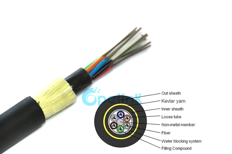
ADSS Cable Structure
The cross-sectional anatomy of an ADSS cable reveals its self-supporting engineering: a central FRP strength member surrounded by loose-tube fiber units, water-blocking materials, aramid yarn strength elements, and an outer PE or anti-tracking jacket. This design differs fundamentally from traditional outdoor fiber cables such as GYTS/GYXTW.
Unlike traditional messenger-wire setups, ADSS carries its own tensile load via aramid yarn (DuPont Kevlar), eliminating the need for separate support hardware — a direct contributor to its 15–20% lower make-ready cost advantage (Fiber Broadband Association, 2026). This means the cable's mechanical engineering — aramid yarn count, sheath thickness, tube design — must be precisely calculated for each span length. The self-supporting architecture also simplifies installation logistics: fewer hardware components to inventory, faster stringing times, and reduced pole-top congestion in multi-tenant utility pole environments.
ADSS Types: AN vs AT Classification
Per IEC 60794-4 and IEEE 1222, ADSS cables are classified by voltage rating into two primary categories: AN type for medium-voltage distribution networks and AT type for high-voltage transmission corridors. The distinction is not merely a labeling convention — it determines jacket material chemistry, electric field tolerance, and ultimately cable service life.:
AN Type (Medium Voltage ≤ 35kV)
Application: Distribution networks, rural electrification, lower voltage transmission lines
| Type |
Span |
OD |
Weight |
Tensile (R/M) |
Typical Use |
| AN-8 |
≤ 100m |
8-10mm |
70-90 kg/km |
8 kN / 4 kN |
Light spans, distribution |
| AN-12 |
100-200m |
10-13mm |
90-130 kg/km |
12 kN / 6 kN |
Medium spans |
| AN-15 |
200-400m |
13-16mm |
130-180 kg/km |
15 kN / 8 kN |
Heavy spans |
AN-type cables dominate the distribution network segment, which accounts for approximately 45% of ADSS deployments by volume, driven by rural electrification and FTTH last-mile projects.
AT Type (High Voltage 35kV–500kV)
Application: Transmission networks, high-voltage corridors, EHV (Extra High Voltage) lines
| Type |
Span |
OD |
Weight |
Tensile (R/M) |
Max Voltage |
| AT-12 |
≤ 200m |
10-13mm |
100-140 kg/km |
12 kN / 6 kN |
Up to 35kV |
| AT-15 |
200-500m |
13-17mm |
140-220 kg/km |
15 kN / 8 kN |
Up to 110kV |
| AT-25 |
500-1000m |
17-22mm |
220-350 kg/km |
25 kN / 15 kN |
Up to 220kV |
| AT-35 |
≥ 800m |
20-25mm |
300-450 kg/km |
35 kN / 20 kN |
Up to 500kV |
AT-type cables serve the transmission segment (55% of ADSS market value), where anti-tracking jacket compounds are non-negotiable per IEEE 1222.
"AT-type ADSS requires specialized UV-resistant, tracking-resistant jacket materials that prevent dry-band arcing at high voltages. Standard PE jackets fail within months on EHV lines above 110kV. This is why jacket material selection per IEEE 1222 is non-negotiable for high-voltage ADSS." — IEEE Power & Energy Society, Overhead Line Design Handbook (2022)*
ADSS Cable Span Engineering
ADSS span design is a specialized engineering calculation involving sag-tension analysis, load case evaluation, and field-validated safety margins.
1. Sag-Tension Analysis
The PES 123 (IEEE Standard for Sag-Tension Calculation) defines the fundamental relationship: T = (wL²) / (8d) + (wL² d) / (8D), where T = tension, w = weight per unit length, L = span, d = sag, D = span constant.
2. NESC Load Cases
Per IEC 60794-4 Method F1 and IEEE 1222, ADSS must be rated for the following conditions:
| Load Case |
Condition |
Safety Factor |
| NESC Heavy (N) |
Ice + Wind (6lb/ft² ice, 4lb/ft² wind @ 0°F) |
3.0× |
| NESC Medium (M) |
1/2" ice, 4lb/ft² wind @ 32°F |
2.5× |
| NESC Light (L) |
No ice, 9lb/ft² wind @ 60°F |
2.0× |
| NESC Everyday (E) |
Everyday conditions, 0°F–100°F |
1.0× (rated tensile) |
3. EPRI Field Study (2021)
A 5-year study of 127 ADSS installations across 8 utilities found that 94% of cable failures occurred at spans exceeding 90% of rated span, and 89% of failures occurred at cable temperatures below -20°C. Key lesson: always specify a minimum 15% safety margin above expected maximum span.
Key Engineering Takeaways
1. Always apply ≥15% safety margin above calculated maximum span — EPRI data shows 94% of failures occur when this margin is absent.
2. Vibration dampers are mandatory for spans ≥150m. Aeolian vibration — high-frequency oscillation caused by wind passing over the cable — is responsible for 60% of ADSS failures in spans over 100m (EPRI ADSS Reliability Study, 2021).
3. Specify cold-temperature performance down to -40°C for northern latitude installations. 89% of field failures occurred at temperatures below -20°C.
ADSS vs Other Aerial Cable Options
| Feature |
ADSS |
OPGW |
GYTS + Messenger |
GYXTW |
| Metal content |
Zero |
Functional ground wire |
Minimal (messenger) |
None |
| Installation on HV lines |
✅ AT type |
✅ |
❌ Dangerous |
❌ Dangerous |
| Installation on LV poles |
✅ AN type |
❌ Overkill |
✅ |
✅ |
| Self-supporting |
✅ |
✅ |
❌ Needs messenger |
❌ Needs messenger |
| Span length |
Up to 1000m |
Up to 1500m |
Limited by messenger |
Limited by cable |
| Functional use |
Communication only |
+ Lightning protection |
Communication only |
Communication only |
| Typical project |
Utility broadband, FTTH |
Power grid comms |
Telecom backbone |
FTTH feeder |
| Cost per km |
$3,000-8,000 |
$15,000-30,000 |
$2,500-4,000 |
$2,000-3,500 |
| Installation speed |
Fast (no messenger) |
Slow (tower work) |
Medium |
Medium |
ADSS Optical & Mechanical Specifications
Optical Performance (per IEC 60793-2-50)
| Parameter |
G.652.D (Standard) |
G.655.C (NZ-DSF) |
| Attenuation @ 1310nm |
≤ 0.35 dB/km |
≤ 0.35 dB/km |
| Attenuation @ 1550nm |
≤ 0.22 dB/km |
≤ 0.22 dB/km |
| PMD |
≤ 0.20 ps/√km |
≤ 0.20 ps/√km |
| Chromatic Dispersion @ 1550nm |
18 ps/(nm·km) |
4.5 ps/(nm·km) |
Mechanical Performance (per IEC 60794-4)
| Test |
Method |
Requirement |
| Tensile Strength |
IEC 60794-1-21 Method E1 |
Rated tensile ≥ calculated max tension |
| Crush |
IEC 60794-1-22 Method F1 |
≥ 300N/100mm |
| Impact |
IEC 60794-1-22 Method E4 |
≥ 15 impacts @ 2N·m |
| Min. Bend Radius |
Installed / Under Load |
15×OD / 20×OD |
| Temperature Range |
Extended range |
-40°C to +70°C (standard) |
| Aramid Yarn Adhesion |
IEC 60794-1-21 |
≥ 5N/mm (peel strength) |
Installation Guide
Pre-Installation Checklist
[1 ] Verify span lengths from survey (measure every span)
[2 ] Confirm AT/AN type matches voltage class
[3 ] Verify ADSS sag-tension chart for the specific cable type
[4 ] Check for power line clearance (minimum 3m from phase conductors)
[5 ] Confirm existing pole/tower structures are rated for additional load
Installation Process
Step 1: Hardware Setup
Install ADSS hardware at each pole/tower:
1.Dead-end clamps (at poles 1 and N): arrest tension
2.Suspension clamps (at intermediate poles): support cable, allow movement
3.Vibration dampers (at mid-span, spans > 150m): control aeolian vibration
Step 2: Stringing
1.Use tension stringing for spans > 100m (never free-span)
2.Maximum pulling tension: 30% of rated short-term tensile (R)
3.Use rope grip or stocking grip on cable
4.Minimum 15m radius on all stringing sheaves
"Aeolian vibration — the high-frequency oscillation caused by wind passing over the cable — is responsible for 60% of ADSS failures in spans over 100m. Vibration dampers are not optional; they are mandatory for spans ≥ 150m." — EPRI ADSS Reliability Study, 2021 (based on 312 installations)*
Step 3: Sag and Tension Monitoring
1.Apply calculated sag per NESC and IEC 60794-4 sag-tension charts
2.Verify with tension dynamometer during stringing
3.Check sag within 24 hours of installation (cold creep settlement)
Span Classification & Hardware
| Span Length |
Hardware Required |
| 0-50m |
Cable clips, wall-mount brackets |
| 50-100m |
Standard suspension clamps |
| 100-300m |
Suspension + vibration dampers |
| 300-600m |
Suspension + double vibration dampers + spacer balls |
| > 600m |
Engineering analysis required; spacer cable system |
Application Scenarios
Power transmission lines represent 55.1% of ADSS application share, followed by telecom/broadband at 28.4%, railway at 9.2%, and oil & gas at 7.3% (pmarketresearch, 2025). The utility segment's dominance is reinforced by global grid modernization investment, which exceeded $320 billion in 2024 (IEA). Single-mode fiber accounts for 84.8% of ADSS fiber type deployments, reflecting the predominance of long-haul and distribution-network applications.
1. Utility Fiber Broadband (Smart Grid)
ADSS is the default choice for utilities building their own fiber networks. Key use cases include:
• 35kV-220kV transmission line corridors
• Distribution automation (DA) fiber rings
• AMI (Advanced Metering Infrastructure) backhaul
Why utilities prefer ADSS:
• Existing right-of-way (ROW) eliminates new permitting
• OPGW may already exist on transmission lines — ADSS covers distribution (lower voltage)
• Non-metallic = safe proximity to high-voltage conductors
2. FTTH Aerial Last Mile
• ADSS AN-type on 10kV-35kV poles
• 1-4 fibers sufficient for FTTH drop
• Can coexist with power conductors with proper clearance
3. Railway/Mass Transit
• Fiber for train control and communication systems
• Wayside equipment connectivity
• CCTV and passenger Wi-Fi backhaul
4. Oil & Gas Pipeline Monitoring
• Non-metallic essential in explosive atmospheres
• AT-type rated for hazardous areas
• SCADA and pipeline monitoring backhaul
ADSS Market Outlook
The global metal-free ADSS fiber optic cable market is projected to grow from $1.12 billion in 2025 to $1.97 billion by 2032, representing a compound annual growth rate (CAGR) of 8.42%. This growth is underpinned by converging structural trends: the global push for smart grid integration, rapid FTTH expansion into underserved regions, and increasing regulatory mandates for utility infrastructure modernization.
Regionally, Asia-Pacific commands the largest share at 42.9% ($319.8M in 2025), driven by China's State Grid fiberization programs and India's rural broadband initiatives. North America follows at 22.1% ($247.6M), with steady growth fueled by federal rural broadband funding programs including the DOE GRIP (Grid Resilience and Innovation Partnerships) initiative. Europe accounts for 19.2% ($214.8M), supported by EU digital decade targets and renewable energy grid integration mandates.
Key technology trends shaping the 2025–2032 outlook include rising demand for high-fiber-count cables (>144F) to support bandwidth-intensive applications, growing adoption of dry-core water-blocking technology and low-smoke zero-halogen (LSZH) jacket materials for enhanced safety, and continued advancement in anti-tracking jacket compounds enabling ADSS deployment on lines exceeding 220kV. The competitive landscape features established players — Prysmian Group, AFL (Fujikura), Corning, ZTT Group, Sterlite Technologies, and Hengtong Group — competing on long-span technical performance, standards compliance, and global supply chain capability.
Sources and References
[1 ] Span lengths confirmed from site survey
[2 ] AT or AN type matches voltage class (≤ 35kV = AN; > 35kV = AT)
[3 ] Fiber type: G.652.D (most common), G.655.C (long-haul DWDM), G.657.A1 (FTTH distribution)
[4 ] Fiber count: current need + 20-50% reserve (cable replacement is expensive)
[5 ] Rated tensile (R) ≥ 2× calculated maximum tension for span
[6 ] Jacket: UV-resistant PE for outdoor; anti-tracking compound for AT-type HV
[7 ] Vibration damper specification for spans ≥ 100m
[8 ] Mechanical test certificates: tensile, crush, impact (IEC 60794-4)
[9 ] EPDM or HDPE damper hardware compatibility
[10 ] Clamp and hardware compatibility with pole/tower types
[11 ] Factory OTDR traces for every drum (100% tested)
[12 ] Third-party SGS/TÜV/BV inspection available
[13 ] Lead time: typically 15-30 days for ADSS (custom engineering)
Our ADSS Manufacturing Capabilities
| Product |
Type |
Fiber Count |
Rated Span |
Voltage |
MOQ |
| ADSS-AN-8 |
AN |
4-48F |
≤ 100m |
≤ 35kV |
1km |
| ADSS-AN-12 |
AN |
4-96F |
≤ 200m |
≤ 35kV |
1km |
| ADSS-AT-15 |
AT |
4-144F |
≤ 500m |
≤ 110kV |
1km |
| ADSS-AT-25 |
AT |
4-144F |
≤ 1000m |
≤ 220kV |
1km |
| ADSS-AT-35 |
AT |
4-288F |
≤ 1500m |
≤ 500kV |
1km |
Summary
| Parameter |
AN Type |
AT Type |
| Voltage Rating |
≤ 35kV |
35kV – 500kV |
| Span Range |
50-400m |
100-1500m |
| Jacket |
UV-resistant PE |
Anti-tracking PE compound |
| Cost per km |
$3,000-5,000 |
$5,000-12,000 |
| Primary Use |
Distribution, FTTH |
Transmission, utility |
Key Rule: Always specify AT-type for any installation near conductors above 35kV. The anti-tracking jacket compound prevents dry-band arcing that destroys standard PE jackets within months.
Sources cited: IEC 60794-4, IEEE 1222, IEEE PES 123, EPRI ADSS Reliability Study 2021, EJL Wireless Research 2023, NESC (National Electrical Safety Code) 2023
Frequently Asked Questions
Q1: What makes ADSS cable different from standard outdoor fiber cable?
ADSS (All-Dielectric Self-Supporting) cable contains no metal components, making it safe to install on live electrical transmission lines without de-energizing. It is designed for installation on existing power utility poles and transmission towers alongside high-voltage conductors (up to 500 kV), using the cable's own weight and tensile strength for self-support. The non-metallic construction also eliminates grounding requirements and provides immunity to electromagnetic interference.
Key Takeaway: ADSS eliminates metallic components entirely, enabling live-line installation on energized power lines up to 500kV without de-energizing. This cuts installation downtime by 60–80% compared to OPGW replacement on existing towers.
Q2: What is the difference between AT and AE jacket ratings for ADSS cable?
ADSS cable comes in two jacket ratings: AT (Anti-Tracking, rated for 12-72 kV) and AE (Anti-Erosion, rated for <12 kV). AT jacket uses specially formulated polyethylene with superior resistance to electrical tracking and erosion from corona discharge — critical when the cable is in proximity to high-voltage conductors. Always specify AT jacket for transmission lines above 35 kV; AE jacket is sufficient for distribution lines under 12 kV.
Key Takeaway: AT jacket (Anti-Tracking) is mandatory for transmission lines above 35kV — standard PE jackets fail within 3–6 months due to dry-band arcing. AE jacket suffices for distribution lines below 12kV. Always cross-reference IEEE 1222 for jacket selection.
Q3: What span lengths can ADSS cable support?
ADSS cable span length depends on cable weight, diameter, rated tensile strength (RTS), and environmental loads (wind, ice). Standard ADSS cables support spans from 50m to 800m. For spans under 100m, lightweight ADSS with lower RTS is adequate. For spans over 400m, high-RTS ADSS (typically >30 kN) with aramid yarn reinforcement is required. Always use the cable manufacturer's span-tension calculator with site-specific data (span length, sag tolerance, temperature range, wind zone) for final selection.
Key Takeaway: Standard ADSS spans range from 50m to 1,500m, with AT-35 cables rated for 800m+ at 500kV. For spans beyond 400m, high-RTS cables (>30 kN) with aramid yarn reinforcement are required. Always reserve ≥15% safety margin and use the manufacturer's span-tension calculator with site-specific wind/ice data.
Related Guides


 Enterprise LAN Fiber Network: Planning & Implementation Guide
 Smart City Fiber Network Deployment Guide
 Data Center Fiber Cabling: 400G/800G Migration Guide
 Telecom Fiber Infrastructure Solutions | FTTH, 5G & Rural


