What Is a PLC Fiber Optic Splitter? Complete Technical Guide
Introduction
A PLC (Planar Lightwave Circuit) fiber optic splitter is a passive optical component that evenly distributes an incoming optical signal from a single input fiber to multiple output fibers. Unlike traditional discrete optical devices, PLC splitters leverage semiconductor-grade photolithography to etch precise waveguide arrays onto silica substrates, enabling highly uniform signal splitting across all output ports.
As a cornerstone of Fiber-to-the-Home (FTTH) and Passive Optical Network (PON) infrastructure, PLC splitters have become indispensable in modern optical communication systems. They operate across a broad wavelength range from 1260 nm to 1650 nm, supporting multiple service wavelengths simultaneously — including 1270 nm, 1310 nm, 1490 nm, 1550 nm, 1577 nm, 1625 nm, and 1650 nm — making them suitable for EPON, GPON, 10G-PON, XGS-PON, and emerging 50G-PON deployments.
The global PLC splitter market reached USD 225.51 million in 2025 and is projected to grow to USD 235.43 million in 2026, reaching approximately USD 346.87 million by 2035 at a compound annual growth rate (CAGR) of 4.4% (Global Growth Insights). Over 60% of FTTH networks worldwide utilize PLC splitters for optical signal distribution, delivering optical signal uniformity improvements of 35% or more compared to legacy alternatives. Furthermore, approximately 30% of new telecommunications infrastructure projects now integrate PLC splitters into their network designs. With global fiber broadband subscriptions growing at nearly 7% annually, the demand for high-quality PLC splitters continues to surge across all major markets.
How PLC Splitters Work — The Planar Lightwave Circuit Principle
PLC is the acronym for Planar Lightwave Circuit — a technology that fabricates optical waveguide structures on a planar substrate using semiconductor manufacturing processes. The core manufacturing flow involves three key steps:
.Photolithography: A mask pattern defining the waveguide geometry is transferred onto a silica-on-silicon wafer using UV exposure, creating the precise Y-branch structures that perform the optical splitting function.
.Etching and Development: The exposed photoresist is developed, and reactive ion etching (RIE) removes unwanted material to form the physical waveguide channels with sub-micron precision.
.Cladding and Encapsulation: A top cladding layer is deposited over the waveguide core to ensure total internal reflection, confining the optical signal within the waveguide paths.The completed PLC chip contains an array of optical waveguides on its upper surface, with the splitting function fully integrated onto a single chip. At both ends of the chip, multi-channel fiber arrays (FAs) are precision-aligned and bonded, coupling the input and output optical paths to external fibers. This monolithic integration approach — combining all optical functions on a single substrate — is the fundamental technology enabling the integration, modularization, and miniaturization of photonic devices.
In contrast to traditional discrete optical components assembled from individual elements, PLC technology consolidates the entire optical power distribution function into a single, compact chip. This yields superior consistency across all output ports, excellent thermal stability, and high reliability — characteristics that make PLC splitters the preferred choice for mass-deployment FTTH and PON networks.
Key Technical Specifications
The performance of a PLC fiber optic splitter is characterized by eight core technical parameters. These specifications are governed by Telcordia GR-1209-CORE and GR-1221-CORE standards, which define the testing and reliability requirements for passive optical components deployed in telecommunications networks. The following table summarizes each parameter, its definition, typical value, and applicable standard reference.
| Parameter |
Description |
Typical Value |
Standard Reference |
| Insertion Loss (IL) |
Reduction in optical power at specified output port relative to total input power; varies by split ratio |
See split-ratio table below |
GR-1209-CORE |
| Return Loss (RL) |
Measure of optical power reflected back along the input path; higher values indicate better performance |
≥ 55 dB (UPC) ≥ 60 dB (APC) |
GR-1209-CORE |
| Uniformity (FL) |
Maximum variation in insertion loss across all output ports within the operating bandwidth |
≤ 0.8 dB (1×8) ≤ 1.5 dB (1×32) |
GR-1209-CORE |
| Polarization Dependent Loss (PDL) |
Maximum output power variation when the polarization state of the transmitted signal changes across all polarization states |
≤ 0.2 dB |
GR-1209-CORE |
| Directivity (DL) |
Ratio of output optical power to injected optical power at the non-injected port on the same side of the device |
≥ 55 dB |
GR-1209-CORE |
| Isolation |
Ability to isolate optical signals between different optical paths; critical for preventing crosstalk in multi-port devices |
≥ 40 dB |
GR-1209-CORE |
| Operating Wavelength |
Wavelength range over which the splitter maintains specified performance across all ports |
1260–1650 nm |
GR-1209-CORE |
| Operating Temperature |
Ambient temperature range within which the device operates reliably without performance degradation |
−40°C to +85°C |
GR-1221-CORE |
Among these parameters, isolation and return loss are particularly significant in practical system deployments. Network operators typically require isolation values of 40 dB or above — failure to meet this threshold can degrade overall system performance through inter-channel crosstalk. Additionally, the long-term stability of the splitter under varying environmental conditions (temperature cycling, humidity exposure) is equally critical; this stability depends directly on the manufacturing process maturity of the fiber optic PLC splitter manufacturer.
Browse OPELINK's full range of PLC splitters — from 1x2 to 1x64, all Telcordia GR-1209/1221 certified.Explore PLC Splitter Solutions
Raw Materials and Manufacturing
The quality and reliability of a PLC fiber optic splitter are fundamentally determined by its two core raw materials and the precision of the manufacturing process.
1. PLC Chip. The PLC chip is fabricated using semiconductor technology — photolithography, etching, and development — to create the optical waveguide array on a silica substrate. The waveguide array resides on the upper surface of the chip, with the shunting function fully integrated at the chip level. The chip design determines the split ratio (1×N or 2×N), insertion loss characteristics, and wavelength performance.
2. Fiber Array (FA). The fiber array is manufactured using precision V-groove substrates — typically silicon or quartz — that position individual optical fibers with sub-micron accuracy. The longitudinal distance error (Deviation) between adjacent fibers is controlled within ±0.5 μm, with a standard center-to-center fiber spacing of 127 μm or 250 μm. The thermal expansion coefficient of the V-groove substrate is matched to the fiber material to ensure stress-free operation and zero fiber displacement at elevated temperatures. End-face angles are precision-ground according to application requirements (typically 0° for UPC or 8° for APC). All fiber arrays comply with Telcordia GR-1209-CORE and GR-1221-CORE standards.
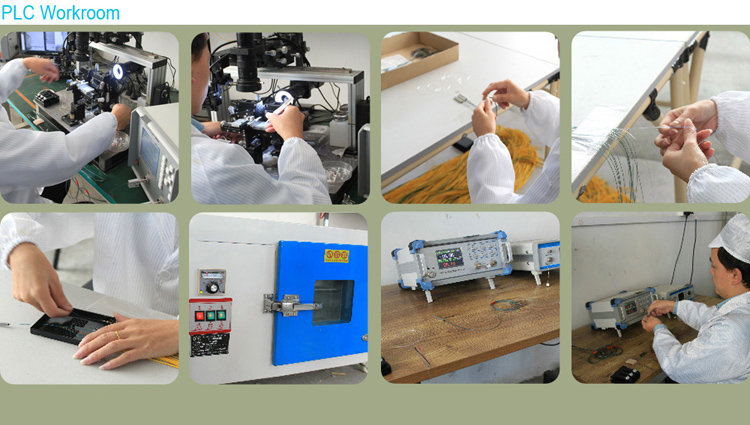
Manufacturing Process — Key Control Points. The most critical step in PLC splitter manufacturing is the precision alignment and bonding of the PLC chip to the input and output fiber arrays using a specialized optical coupling adhesive. This alignment process — often referred to as active alignment — requires sub-micron positioning accuracy across all channels simultaneously to minimize insertion loss and ensure uniformity. After assembly, every PLC splitter undergoes a rigorous burn-in and aging cycle (thermal cycling from −40°C to +85°C) in full compliance with Telcordia GR-1209-CORE and GR-1221-CORE reliability testing protocols. Only units that pass these environmental stress tests are released for shipment.
PLC vs. FBT Splitters: A Comprehensive Comparison
When designing optical distribution networks, engineers face a fundamental choice between two splitting technologies: Planar Lightwave Circuit (PLC) and Fused Biconical Taper (FBT). While both serve the same basic function — dividing optical signals — they differ substantially in manufacturing approach, performance characteristics, cost structure, and optimal application scenarios.
Technology Comparison
| Feature |
PLC Splitter |
FBT Splitter |
| Technology |
Photolithographic waveguide etching on silica substrate |
Fused biconical tapering — fibers heated and stretched |
| Wavelength Range |
1260–1650 nm (full spectrum, wavelength-insensitive) |
Single or dual window (e.g., 1310 nm or 1310/1550 nm) |
| Splitting Uniformity |
Excellent — ≤0.8 dB variation across ports |
Poor — up to 7 dB variation possible |
| Maximum Split Ratio |
1×64 standard; 1×128 emerging |
1×8 natively; cascaded up to 1×32 (degraded performance) |
| Temperature Stability |
−40°C to +85°C (full outdoor range) |
−5°C to +75°C (limited range) |
| Cost at 1×8 |
USD 3–4 per port |
USD 2–3 per port (30–40% cheaper) |
| Cost at 1×32 |
USD 1.25 per port (PLC dominant) |
Higher cost; requires cascading multiple FBTs |
| Form Factor |
Compact — 12 mm module width |
Larger — ~24 mm per unit |
| Failure Rate (Harsh Environments) |
Lower — 34% fewer field failures in extreme climates |
Higher — more temperature-sensitive |
| Manufacturing Method |
Automated wafer processing (100+ chips per batch) |
Labor-intensive manual fusion (12+ hours per unit) |
Market Dynamics
In terms of market share distribution, single-mode FBT splitters account for approximately 55% of total splitter unit volume but only 40% of market value — a reflection of their lower per-unit cost at low port counts. The market share breakdown by split ratio reveals a clear competitive landscape:
.1×4 splitters: FBT dominates with 80% market share — lowest cost and sufficient performance for this configuration
.1×8 splitters: FBT holds 60% market share — remains cost-competitive, though PLC is gaining
.1×16 splitters: FBT drops to approximately 20% — performance advantages of PLC become decisive
.1×32 splitters: FBT holds less than 5% — PLC is virtually the only choice for operators at this ratioFor GPON and EPON networks — where 1×32 is the typical final-stage split ratio — PLC splitters dominate entirely. In XGS-PON deployments, some operators employ a hybrid architecture: 1×4 FBT at the street cabinet plus 1×8 PLC at the building entry, optimizing both cost and performance within the available optical power budget.
Selection Guidelines
.1×2 to 1×8 — Choose FBT: Best cost-performance ratio for distributed PON architectures, monitoring taps, and applications not requiring wide-wavelength operation.
.1×16 and above — Choose PLC: Lower insertion loss, superior uniformity, and dramatically better scalability for mass FTTH deployments.
.XGS-PON / 50G-PON — PLC Mandatory: Tighter optical power budgets and wavelength requirements demand the performance characteristics of PLC technology.
.Hybrid Approach — 1×4 FBT (street cabinet) + 1×8 PLC (building entry): Increasingly popular for cost-optimized distributed split architectures in suburban and rural deployments.
.Harsh Environments — Choose PLC: With operating temperature range of −40°C to +85°C and 34% lower field failure rates, PLC is the only reliable choice for outdoor (OSP) deployments.
Looking for cost-effective FBT splitters for your 1x4/1x8 deployments? View OPELINK's FBT splitter lineup.FBT Splitter
Product Types and Form Factors
PLC fiber optic splitters are available in seven primary packaging configurations, each optimized for specific deployment scenarios, space constraints, and connectivity requirements. The choice of form factor directly impacts installation complexity, maintenance accessibility, and overall network total cost of ownership (TCO).
a. Bare Fiber PLC Splitter — The bare fiber configuration directly fans out the optical fibers (typically ribbon fiber) from the PLC chip without connectors on either end. In field applications, fusion splicing is used for access, making it ideal for installation into conventional splice closures, splice trays, and optical fiber distribution panels. This form factor is primarily suited for space-constrained environments where infrequent reconfiguration is expected, such as optical cable splice boxes and fiber distribution trays.
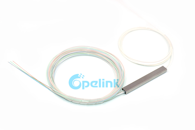
b. Fanout PLC Splitter — The fanout configuration builds upon the bare fiber splitter by adding a small splitter enclosure box with 0.9 mm sleeved output fibers. The enclosure can be fixed to mounting surfaces, providing mechanical protection to the bare splitter assembly while maintaining a compact footprint.
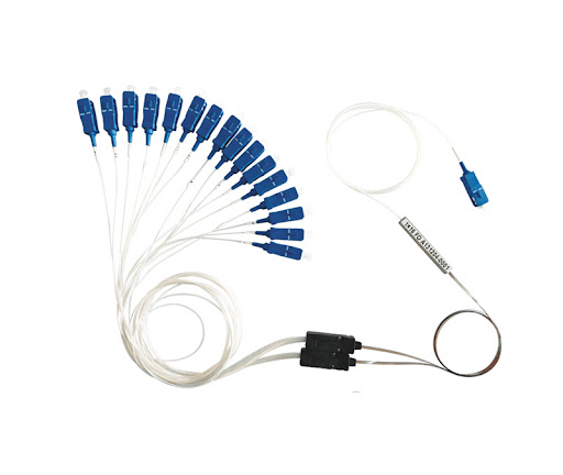
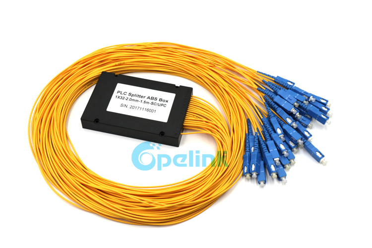
c. ABS Cassette PLC Splitter — Encapsulated in a rugged ABS plastic box, this type routes ports via pigtails with outer diameters of 0.9 mm, 2.0 mm, or 3.0 mm. The cassette form factor imposes minimal placement constraints and can be installed inside optical cable junction boxes, corridor distribution boxes, or fiber distribution boxes. View ABS Cassette PLC Splitter product
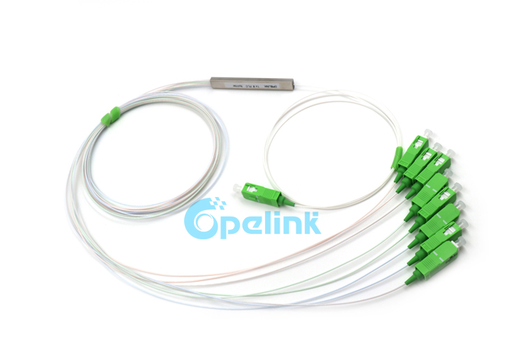
d. Micro Pigtail PLC Splitter — Also known as Mini Blockless PLC Splitter, this ultra-compact design packages the splitter in a 4 mm steel tube with 0.9 mm loose-tube pigtails. Its minimal form factor is specifically engineered for high-density installations where space is at a premium, such as optical cable splice closures, fiber splitter boxes, and cassette-type or rack-mount combination enclosures. View 1×8 Micro PLC Splitter product
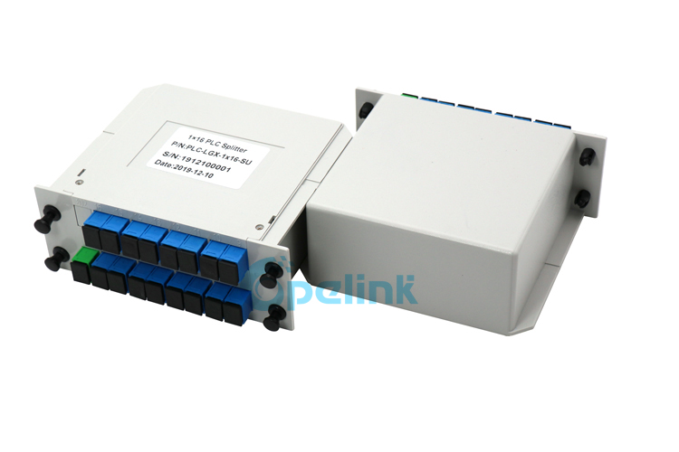
e. Cassette Type PLC Splitter (LGX) — This plug-in cassette form factor is enclosed in an ABS plastic housing with front-facing connector ports for easy access. It is primarily installed in optical fiber distribution frames and junction boxes that support LGX-compatible mounting. The modular, hot-swappable design simplifies network maintenance and capacity upgrades. View LGX Cassette PLC Splitter product
f. Tray-Type PLC Splitter — The tray-type splitter uses a plastic tray enclosure similar in design to a fiber distribution panel. The front panel features one or two FC (or SC) adapters serving as optical input ports, with multiple FC (or SC) adapters for output ports. Its compact, plug-and-play design enables installation in optical cable transfer boxes and ODF racks, facilitating unified management of splitters alongside optical wiring. View Tray-Type PLC Splitter product
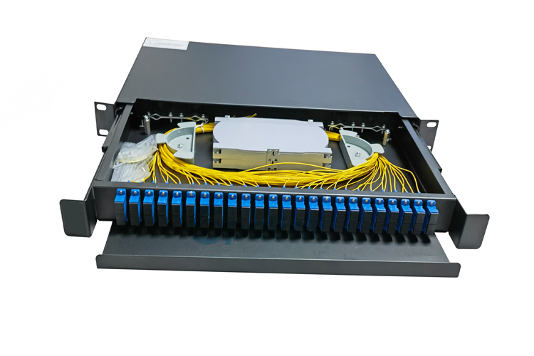
g. Rack-Mounted PLC Splitter — Encased in a rugged metal chassis, the rack-mounted splitter is designed for installation in standard 19-inch 1U racks. It is primarily deployed in optical cable distribution boxes, optical distribution frames (ODFs), and central office (CO) environments where high port density, organized cable management, and front-panel accessibility are required. View 2×64 Rack-Mount PLC Splitter product
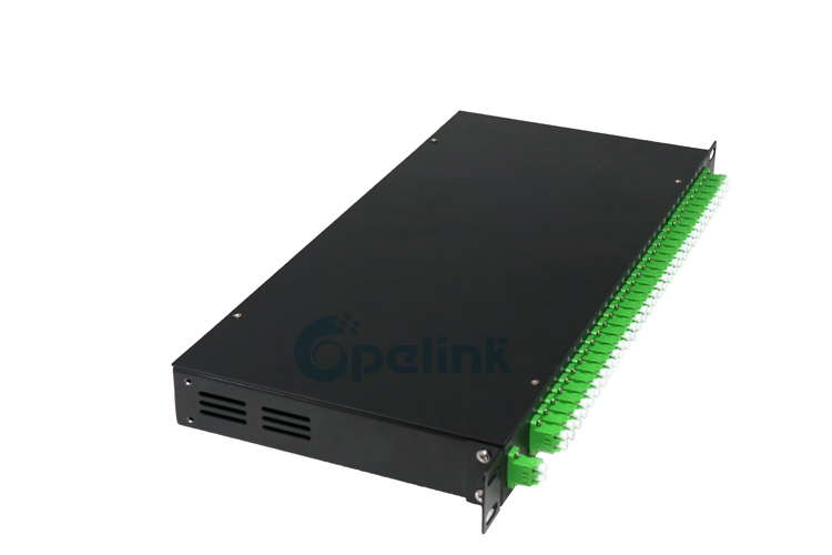 Our best-selling 1x8 PLC Splitter delivers <10.5 dB insertion loss and superior uniformity.1x8 fiber optic plc splitter
Industry Trends and Future Outlook
The PLC splitter landscape is undergoing transformative changes driven by next-generation PON standards, miniaturization demands, and innovative network topologies. Network architects and procurement managers must understand these trends to future-proof their optical distribution network (ODN) investments.
50G-PON Evolution. As operators migrate from GPON to XGS-PON and eventually 50G-PON (ITU-T G.9804 series), the optical power budget becomes significantly tighter with each generation. Every decibel saved in the passive ODN allows for an additional 2–3 kilometers of reach or the accommodation of extra mechanical splices without breaching the receiver sensitivity threshold. This drives demand for premium-grade, low-loss PLC splitters.
| Split Ratio |
Typical Loss (dB) |
Max IL — Premium (dB) |
| 1:8 |
9.8 |
10.2 |
| 1:16 |
13.1 |
13.5 |
| 1:32 |
16.2 |
16.5 |
| 1:64 |
19.5 |
20.1 |
Note: Calculations include SC/APC connector loss based on 2026 manufacturing tolerances (G.657.A1 fiber).
Micro-Miniaturization. Micro-plug-in (Mini) splitters with 4 mm steel tube packaging have become essential components for high-density splice closures. With the widespread adoption of air-blown fiber systems, these ultra-compact splitters are now integrated directly into micro-duct manifolds, enabling installers to push fiber and splitters simultaneously through pre-installed micro-duct networks. This approach reduces both deployment time and labor costs for last-mile FTTH connections.
Non-Uniform PLC Splitters. An emerging trend in bus-topology rural fiber builds, non-uniform (asymmetric) PLC splitters allow different percentages of optical power to be dropped at various points along a single fiber strand. This architecture combines the deployment efficiency of FBT-style tapped topologies with the thermal stability and reliability of PLC technology — an ideal solution for long-distance rural networks where housing density is low and fiber spans are long.
Ultra-High-Density (UHD) LGX Modules. For central office (CO) and data center environments where rack space is at a premium, UHD LGX cassettes now house four 1×32 splitters in a single 1U rack space — quadrupling port density compared to the previous generation. This density improvement directly translates to lower per-port CO real estate costs and simplified cable management in high-port-count deployments.
SC/APC Standardization. The industry is converging on SC/APC (green connector) as the mandatory standard for all new PLC splitter deployments. The 8° angle-polish provides a return loss exceeding 60 dB — critical for preventing back-reflections that can induce instability and damage in high-power 50G-PON transmitters. Unless a specific legacy infrastructure constraint exists, network architects should specify SC/APC connectors for all new ODN builds.
Application Scenarios
PLC fiber optic splitters are deployed between the Optical Line Terminal (OLT) at the central office and the Optical Network Terminals (ONTs) or Optical Network Units (ONUs) at subscriber premises within passive optical networks. They are compatible with all major PON standards:
.Broadband PON (BPON) — ITU-T G.983
.Gigabit PON (GPON) — ITU-T G.984
.Ethernet PON (EPON) — IEEE 802.3ah
.10G-EPON — IEEE 802.3av
.10G-PON (XG-PON) — ITU-T G.987
.10G Symmetric PON (XGS-PON) — ITU-T G.9807.1
.50G-PON — ITU-T G.9804 series (emerging)
Two primary deployment architectures exist for PLC splitters in PON networks:
Centralized Splitting: A single-stage 1×N splitter is placed near the OLT at the central office, with dedicated feeder fibers running directly from the splitter to each subscriber location. This architecture simplifies network monitoring and fault isolation but requires more fiber infrastructure. It is most cost-effective in dense urban deployments with short fiber runs.
Distributed (Cascaded) Splitting: A two-stage splitting topology — for example, a 1×4 splitter at the central office or street cabinet, followed by 1×8 splitters near end-user clusters — effectively creates a 1×32 distribution. This approach significantly reduces fiber consumption, supports gradual network expansion, and is the dominant architecture in suburban, rural, and emerging-market FTTH rollouts.
With the continued expansion of FTTH networks worldwide — driven by government broadband initiatives such as the U.S. BEAD program (targeting 25 million rural homes passed by 2028) and China's Double Gigabit Cities initiative — PLC splitters have become the most widely deployed passive optical component in access networks. Their advantages of high split counts, uniform light distribution, and compact form factor make them the preferred choice for operators scaling their fiber infrastructure to serve an ever-growing subscriber base.
FAQ
Q1: What is a PLC fiber optic splitter and how does it work?
A PLC (Planar Lightwave Circuit) fiber optic splitter is a passive optical component that evenly divides an incoming optical signal into multiple output fibers using photolithographically-etched waveguide technology on a silica substrate. Unlike traditional fused biconical taper (FBT) splitters, PLC splitters leverage semiconductor fabrication processes to create precise Y-branch waveguide structures, ensuring superior splitting uniformity across all output ports. With support for wavelengths from 1260 nm to 1650 nm and split ratios up to 1x64, PLC splitters serve as the backbone of modern FTTH and PON networks, with over 60% of global FTTH deployments relying on PLC technology for optical signal distribution.
Key Takeaway: PLC splitters use semiconductor-grade waveguide technology to deliver wavelength-independent, uniform optical splitting — making them the industry standard for scalable fiber optic networks.
Q2: PLC splitter vs FBT splitter: which one should I choose?
The choice depends on your split ratio, budget, and deployment environment. FBT splitters dominate low-port-count applications: they hold 80% market share for 1x4 and 60% for 1x8 configurations, offering a 30-40% cost advantage over PLC at these ratios. However, FBT's market share drops to below 5% at 1x32, where PLC splitters are virtually the only viable option. For FTTH/PON networks requiring 1x16 or higher, PLC is the clear winner due to superior insertion loss, uniformity, and wavelength insensitivity. For XGS-PON and 50G-PON deployments, PLC is mandatory. A hybrid approach — 1x4 FBT at the street cabinet plus 1x8 PLC at the building entry — is increasingly popular for cost-optimized distributed architectures.
Key Takeaway: Choose FBT for 1x8 and below (cost leader); choose PLC for 1x16 and above, XGS-PON, and any deployment requiring wavelength flexibility or environmental robustness.
Q3: What are the latest trends in PLC splitter technology for 2026?
Three transformative trends are reshaping the PLC splitter landscape in 2026. First, the evolution toward 50G-PON imposes tighter optical power budgets, driving demand for premium low-loss PLC splitters (e.g., 1:32 at 16.5 dB max IL). Second, micro-miniaturization: 4 mm steel-tube mini splitters are now integrated directly into micro-duct manifolds for air-blown fiber systems, supporting ultra-dense deployments. Third, non-uniform PLC splitters are emerging for bus-topology rural fiber builds, enabling flexible power distribution along a single fiber strand. Additionally, UHD LGX modules now pack four 1x32 splitters into a single 1U rack space, and SC/APC connectors with >60 dB return loss have become the mandatory standard across the industry.
Key Takeaway: 50G-PON readiness, micro-miniaturization, non-uniform splitting, and UHD packaging define the 2026 PLC splitter innovation frontier.
Related Guides

 Outdoor Fiber Optic Cable Installation Guide: Aerial, Duct & Direct Burial Methods
 Outdoor Fiber Optic Cable Types: GYTS, ADSS and OPGW Guide
 ADSS Cable for 110kV Power Line: Specifications, Selection & Pricing Guide
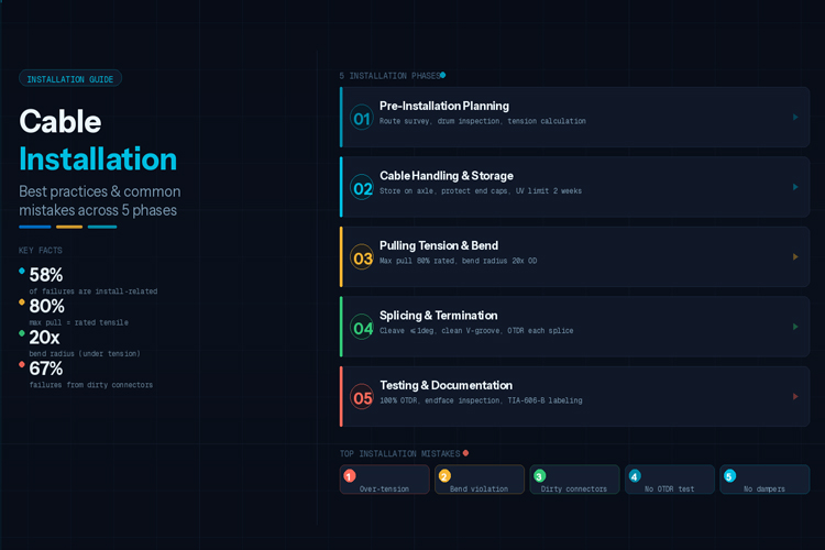 Fiber Cable Installation Best Practices & Common Mistakes


