English
Welcome to opelink.com
Industry News

Optimization of Waveguide Structure Design for PLC Chips

Views : 1483
Update time : 2024-07-15 10:34:54
Light propagates in waveguides that are made by incorporating a high refractive index core surrounded by a low refractive index cladding material. Optical waveguides allow efficient routing of optical signals between different components on photonic integrated circuits (PICs). Optimization of the waveguide structure can help reduce insertion losses and crosstalk.
 
The most common type of waveguides used in PLC chips are silicon nitride (SiN) and silicon-on-insulator (SOI) waveguides. Techniques for optimizing the design of these waveguide structures include:

 
Optimizing the Waveguide Cross Section
The standard rectangular cross section for PLC waveguides can be optimized to reduce losses. Waveguide cross sections with smoother corners like trapezoidal or inverted trapezoidal shapes reduce scattering losses.
These shapes allow for adiabatic tapering of the waveguide mode, resulting in lower insertion loss. SiN waveguides with optimized trapezoidal cross sections have demonstrated 0.4 dB/cm lower insertion loss compared to rectangular cross sections.
 

Optimizing Bend Radii
Bends in waveguides result in losses due to radiative bend loss and waveguide mode mismatch at the bends. Reducing the bend radius and optimizing the shape of the bend waveguide structure can reduce bend losses.
SOI waveguides with optimized annular bends have shown up to 2.6x lower bend loss compared to straight bends. Similarly, rounded bends in SiN waveguides have exhibited up to 3 dB lower losses compared to rectangular bends.
 

Optimizing Waveguide Tapers
Gradual tapers are used to transition between waveguides of different widths. Optimized taper shapes allows adiabatic transition of the waveguide mode resulting in lower losses.
'S' shaped tapers have demonstrated the ability to reduce losses to as low as 0.02 dB. Compound parabolic tapers have shown 0.02-0.03 dB lower loss compared to linear tapers.
 

Optimizing Intersection Structures
Waveguide intersections are used for splitting and combining optical signals. Improving the intersection geometry and using tapered sections can reduce insertion losses.
Splitters with optimized intersection angles and additional bends have shown losses as low as 0.06 dB compared to 0.12 dB for standard designed splitters.
 
In summary, optimizing the geometry of different waveguide structures such as bends, tapers, cross sections and intersections can help minimize insertion losses and crosstalk in PLC chips. With these techniques, losses below 0.1 dB/intersection and 0.4 dB/cm have been achieved.
 

Key Words: PLC waveguides, waveguide optimization, SiN waveguides, SOI waveguides, waveguide bend loss
 

FAQs
Q1: What is the cause of bend losses in PLC waveguides?
A1: Bend losses in PLC waveguides occur due to two main reasons:
1.Radiative bend loss: Due to the curvature of the bend, some of the optical power couples out of the waveguide core and propagates as radiation. This leads to losses.
2.Mode mismatch loss: There is a mode mismatch between the straight and curved portions of the bend waveguide. Some of the power from the guided mode couples into higher order cladding modes, resulting in losses.
 
Q2: What is the difference between SiN and SOI waveguides?
 
A2:
.SiN waveguides use silicon nitride as the core material and silicon dioxide as the cladding. They have lower propagation losses (~0.1 dB/cm) compared to SOI waveguides.
 
.SOI waveguides use a thin silicon layer on an insulator (silicon dioxide) as the core. They have a higher index contrast which allows for tighter bends and compact devices. However, they suffer from higher propagation losses (~0.5 dB/cm).
 
Q3: How can waveguide tapers reduce losses?
A3: Tapers with a gradual transition between the two widths allow an adiabatic mode transformation. This means that the optical mode smoothly adapts its shape as it propagates through the taper, minimizing coupling to higher order modes. This results in lower transition losses compared to abrupt transitions.
Optimized taper shapes like 'S' tapers and compound parabolic tapers ensure a more adiabatic transformation, achieving losses as low as 0.02 dB.
 
Q4: What is the role of waveguide intersections in PLC chips?
A4: Waveguide intersections are used to split or combine optical signals on PLC chips. They are used to implement the following functions:
1.Power splitters/combiners
2.Directional couplers
3.Multimode interferometers (MMIs)
4.Arrayed waveguide gratings (AWGs)
Optimizing the geometry of the intersections can reduce the insertion losses to as low as 0.06 dB.
 
Q5: What are the key advantages of PLC over other photonic integration platforms?
A5:
.Low cost: PLCs use standard lithography and etching techniques which are low cost.
.High volume production: PLC fabrication is compatible with high volume CMOS foundry processes.
.Compact size: Dense integration of components is possible due to smaller bend radii.
.CMOS compatibility: PLC platforms use materials like silicon dioxide and silicon nitride which are compatible with CMOS. This enables monolithic integration with silicon electronics.

 
Related News
Read More >>
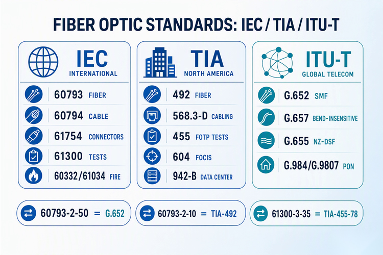
Fiber Optic Cable Standards: IEC/TIA/ITU Complete Guide Fiber Optic Cable Standards: IEC/TIA/ITU Complete Guide
Aug .18.2026
2026 fiber optic cable standards reference: IEC 60793, TIA-568.3-D, ITU-T G.652-G.657 specifications for single-mode and multimode fiber, cable construction standards, connector interfaces, and testing methods.
Fiber Optic for CCTV & Security: Long-Distance Surveillance Guide Fiber Optic for CCTV & Security: Long-Distance Surveillance Guide
Aug .11.2026
2026 guide to fiber optic CCTV & security surveillance: long-distance architecture, 4K/8K bandwidth planning, fiber cable selection, city-wide deployment strategies, and NDAA-compliant equipment selection.
Railway & Mass Transit Fiber Communication Systems Guide Railway & Mass Transit Fiber Communication Systems Guide
Aug .03.2026
Railway fiber optic communication systems for CBTC/ERTMS train control, trackside GYTC8S cable installation, metro fiber backbones, and high-speed rail networks. Covers EN 50128 fire safety and UIC 303 standards.

Oil & Gas Fiber Optic: Explosive-Proof Cabling Solutions Guide Oil & Gas Fiber Optic: Explosive-Proof Cabling Solutions Guide
Jul .21.2026
ATEX/IECEx fiber optic cables for oil and gas hazardous areas: downhole DTS/DAS sensing, pipeline leak detection, offshore platform networking, and GYFTZY non-metallic cable selection. Explore OPELINK's 2026 explosive-proof fiber solutions guide.