Key Takeaways
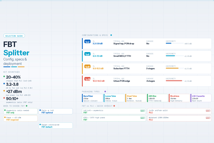
- FBT splitters cost 20-40% less than PLC equivalents for 1x2 to 1x8 configurations, making them the default choice for cost-sensitive PON deployments where split ratios stay at or below 1x8. At 1x16 and above, PLC becomes more economical per port due to FBT's cascading losses.
- FBT splitters support asymmetric splitting ratios (1:99 to 50:50) -- a capability PLC cannot match without custom (and expensive) waveguide redesign. This makes FBT the only viable option for optical power monitoring taps, signal tapping, and unequal distribution in CATV + data hybrid networks.
- A 1x2 FBT splitter typically achieves 3.2-3.8 dB insertion loss with excess loss below 0.1 dB, outperforming PLC's 3.8-4.2 dB at the same ratio. For short-reach access drops under 5 km, this 0.5-1 dB advantage directly extends link budget headroom.
- FBT splitters handle optical power up to +27 dBm -- 3-7 dB higher than PLC's +20-23 dBm saturation limit. This is critical for EDFA-boosted long-reach PONs and CATV analog video overlays where high launch power is standard.
- The selection decision is straightforward: direct burial or outdoor cabinet -> FBT with steel tube housing; indoor distribution box -> FBT with ABS box or blockless; monitoring/tap application -> asymmetric ratio FBT; high-density 1x32+ urban FTTH -> switch to PLC. When in doubt for 1x8 and below, FBT is the default.
Introduction
Fused Biconical Taper (FBT) splitters are the workhorse of passive optical signal distribution in fiber-to-the-home (FTTH), CATV, and telecom monitoring networks. Manufactured by fusing and stretching two or more optical fibers under controlled heat, FBT splitters divide a single optical input into multiple outputs at a defined ratio -- without electrical power, moving parts, or complex waveguide fabrication.
This guide focuses on the practical selection problem: given a specific deployment scenario, which FBT splitter configuration, packaging type, wavelength window, and coupling ratio should you specify? We provide specification tables, a decision framework, and application-specific recommendations drawn from IEC 61753-1, Telcordia GR-1209/GR-1221, and ITU-T G.652 standards.
How FBT Splitters Work: A Concise Technical Summary
An FBT splitter is manufactured by:
- Stripping the coating from two or more optical fibers and twisting them together
- Fusing the bundled fibers under an electric arc or hydrogen flame while simultaneously stretching (tapering) them
- Monitoring the coupling ratio in real-time during the tapering process until the target split ratio (e.g., 50:50, 90:10) is achieved
- Packaging the fused region into a protective substrate (steel tube, ABS module, or bare fiber sleeve)
The tapered fusion region causes the fiber cores to come into close proximity, allowing evanescent field coupling -- light transfers from the input fiber core to adjacent fiber cores based on the taper geometry. The splitting ratio is determined by:
- Taper length -- longer tapers produce more complete coupling
- Fusion temperature -- affects the refractive index profile of the fused region
- Pulling speed -- controls the taper profile and transition losses
The result is a fully passive device with no electrical requirements, capable of operating for 20+ years in stable environments with MTBF exceeding 10^6 hours per Telcordia GR-1209.
FBT Splitter Configurations
| Configuration |
Typical Application |
Cascaded? |
Insertion Loss (Typical) |
Uniformity |
| 1x2 |
Signal tap, basic PON drop, monitoring |
No |
3.2-3.8 dB |
<0.5 dB |
| 1x3 |
Custom PON, non-standard splits |
No |
5.0-5.5 dB |
<0.8 dB |
| 1x4 |
Small MDU, FTTH distribution |
No |
6.5-7.0 dB |
<1.0 dB |
| 1x8 |
Suburban FTTH, medium PON |
Yes (3 stages) |
9.5-10.5 dB |
<1.5 dB |
| 1x16 |
Urban PON edge |
Yes (4 stages) |
13.0-14.0 dB |
<1.8 dB |
| 1x32 |
Legacy GPON (cost-sensitive) |
Yes (5 stages) |
16.5-18.0 dB |
<2.5 dB |
By Port Count
Note: For 1x32 and above, PLC splitters are strongly recommended. Cascaded FBT at 1x32 suffers from accumulated excess loss (0.2-0.5 dB per cascade stage) and uniformity degradation up to +/-2.5 dB between ports.
| Type |
Wavelength Range |
Best For |
Cost Premium |
| Single-window |
1310 nm or 1550 nm (+/-40 nm) |
Standard GPON/EPON, single-purpose links |
Baseline |
| Dual-window |
1310 & 1550 nm simultaneously |
GPON + CATV video overlay, mixed services |
+10-15% |
| Triple-window |
1310, 1490 & 1550 nm |
Full GPON triple-play (data + voice + video) |
+20-25% |
| Wideband |
1260-1620 nm (flat response) |
CWDM systems, future NG-PON2 upgrade |
+30-40% |
By Wavelength Window
| Type |
Wavelength Range |
Best For |
Cost Premium |
| Single-window |
1310 nm or 1550 nm (+/-40 nm) |
Standard GPON/EPON, single-purpose links |
Baseline |
| Dual-window |
1310 & 1550 nm simultaneously |
GPON + CATV video overlay, mixed services |
+10-15% |
| Triple-window |
1310, 1490 & 1550 nm |
Full GPON triple-play (data + voice + video) |
+20-25% |
| Wideband |
1260-1620 nm (flat response) |
CWDM systems, future NG-PON2 upgrade |
+30-40% |
By Coupling Ratio
| Ratio |
Primary Use Case |
Notes |
| 50:50 |
Equal signal distribution (standard PON) |
Most common, lowest cost, best availability |
| 90:10 |
Optical power monitoring / signal tap |
90% to traffic path, 10% to monitoring detector |
| 95:5 |
Low-intrusion signal sampling |
Minimal impact on main path budget |
| 99:1 |
High-sensitivity tap / test access |
Used in OTDR monitoring and fault detection |
| 80:20 / 70:30 |
Asymmetric distribution |
Mixed-service networks with unequal bandwidth allocation |
Key advantage: Asymmetric ratios are a native FBT capability -- the taper geometry is simply adjusted during manufacturing. PLC splitters require custom waveguide redesign for asymmetric splits, with significantly higher cost and longer lead times.
By Packaging Type
| Package |
Dimensions (Typical) |
Environment |
Connector Options |
Best For |
| Bare fiber (250um) |
25mm x 2.5mm |
Splice closure, distribution box |
None (fusion splice) |
High-density cassettes, lowest cost |
| Loose tube (900um) |
40mm x 3mm |
Indoor trays, patch panels |
SC, LC, FC, ST |
Indoor distribution, easy handling |
| Steel tube (3.0mm) |
50mm x 3mm |
Outdoor, direct burial, harsh |
SC/APC, LC/UPC |
Outdoor cabinets, aerial, industrial |
| ABS box |
100x60x15mm |
Wall mount, ODF, FTTH terminal |
SC/APC duplex |
FTTH drop, subscriber terminal |
| Blockless (mini) |
38x4x4mm |
High-density cassettes, LGX |
LC/UPC |
Data center, metro access |
| LGX cassette |
120x80x10mm |
Rack mount, 1U panels |
LC duplex |
Central office, OLT distribution |
Key Specifications Explained
Insertion Loss (IL)
The total optical power lost when a signal passes through the splitter, measured in dB. For a 1x2 FBT at 50:50 ratio:
- Theoretical minimum: 3.01 dB (10 x log10(2))
- Typical FBT: 3.2-3.8 dB (excess loss 0.1-0.5 dB)
- Specification grade: <=3.6 dB typical, <=4.0 dB maximum
Always specify both typical and maximum values in procurement. The maximum value is what your link budget must account for.
Excess Loss
The insertion loss above the theoretical minimum. For quality FBT splitters:
| Configuration |
Excess Loss (Typical) |
Excess Loss (Max) |
| 1x2 |
<=0.1 dB |
<=0.2 dB |
| 1x4 |
<=0.2 dB |
<=0.4 dB |
| 1x8 |
<=0.4 dB |
<=0.6 dB |
| 1x16 |
<=0.6 dB |
<=1.0 dB |
Uniformity
The variation in insertion loss between output ports. Lower is better.
- 1x2 FBT: <0.5 dB (excellent)
- 1x4 FBT: <1.0 dB (good)
- 1x8 FBT: <1.5 dB (acceptable)
- 1x16 FBT: <1.8 dB (marginal -- consider PLC)
- 1x32 FBT: <2.5 dB (poor -- use PLC)
Polarization Dependent Loss (PDL)
The variation in insertion loss with input polarization state. FBT splitters achieve very low PDL:
- Typical: <=0.1 dB
- Maximum: <=0.15 dB
This is comparable to or better than PLC splitters, making FBT suitable for polarization-sensitive applications.
Return Loss (RL) and Directivity
| Parameter |
FBT Typical |
Standard Requirement |
| Return Loss |
>=55 dB |
>=50 dB (Telcordia GR-1209) |
| Directivity |
>=55 dB |
>=50 dB |
High return loss (>50 dB) prevents reflected light from degrading upstream laser stability -- critical in GPON OLT protection.
Operating Temperature
- Operating: -40C to +85C
- Storage: -40C to +85C
- Temperature-dependent loss drift: <0.5 dB over full range
FBT Splitter Selection Framework
Decision Table: Scenario to Recommended Configuration
| Your Scenario |
Recommended FBT Type |
Housing |
Ratio |
Wavelength |
| GPON 1x2 drop, <5 km |
1x2 single-window |
Steel tube or bare |
50:50 |
1310/1490 nm |
| GPON 1x4, small MDU |
1x4 single-window |
ABS box |
50:50 |
1310/1490 nm |
| Suburban FTTH 1x8 |
1x8 dual-window |
ABS box |
50:50 |
1310&1550 nm |
| CATV + data hybrid |
1x2 dual-window |
Steel tube |
90:10 or 80:20 |
1310&1550 nm |
| Optical monitoring / tap |
1x2 single-window |
Bare fiber |
95:5 or 99:1 |
Per system |
| OTDR test access |
1x2 single-window |
Loose tube |
99:1 |
1310/1550 nm |
| Outdoor cabinet, 1x4 |
1x4 single-window |
Steel tube (IP67) |
50:50 |
1310 nm |
| Data center fan-out |
1x4 or 1x8 wideband |
Blockless/LGX |
50:50 |
1260-1620 nm |
| Legacy GPON 1x32 (budget) |
1x32 cascaded |
ABS box |
50:50 |
1310/1490 nm |
| Aerial deployment |
1x2 or 1x4 |
Steel tube + UV jacket |
50:50 |
Per system |
Selection Checklist
Before specifying an FBT splitter, confirm:
- Split ratio -- equal (50:50) or asymmetric? If asymmetric, FBT is the only practical choice
- Port count -- 1x8 or below? FBT is optimal. 1x16? FBT acceptable. 1x32+? Consider PLC
- Wavelength -- single, dual, or wideband? Match to your laser sources
- Link budget -- calculate total IL including connectors and splice losses; verify ONU sensitivity margin
- Environment -- indoor (ABS/bare) vs outdoor (steel tube) vs harsh (steel tube + IP67)
- Connector type -- SC/APC (most common for PON), LC/UPC (high density), or bare fiber (fusion splice)
- Fiber type -- G.652.D (standard SMF) or G.657.A1 (bend-insensitive for tight bends in FTTH)
- Compliance -- require Telcordia GR-1209/GR-1221 test report and per-drum OTDR trace
Application Scenarios in Detail
1. PON / FTTH Distribution (1x2 to 1x8)
The most common FBT application. In a GPON network, the OLT transmits at 1490 nm downstream and receives at 1310 nm upstream. A 1x8 FBT splitter with dual-window (1310 & 1490 nm) operation distributes the OLT signal to 8 ONUs, each receiving approximately 12.5% of the input power.
Spec example for GPON 1x8: Insertion loss <=10.5 dB (max); Uniformity <=1.5 dB; Wavelength: 1310 & 1490 nm dual-window; Return loss >=55 dB; Housing: ABS box with SC/APC connectors; Fiber: G.657.A1 (bend-insensitive for FTTH drop).
2. CATV Video Overlay
In triple-play networks, a 1550 nm analog CATV signal is overlaid on the GPON data. An FBT splitter with dual-window (1310 & 1550 nm) or triple-window (1310, 1490 & 1550 nm) operation is required. For CATV applications where video carries higher priority, an asymmetric ratio (e.g., 80:20) directs more power to the video path while maintaining data connectivity on the lower-power port.
3. Optical Power Monitoring / Signal Tapping
FBT splitters with asymmetric ratios (95:5 or 99:1) are the industry standard for in-service optical monitoring. This is a FBT-exclusive application -- PLC splitters cannot economically produce asymmetric ratios. Network monitoring systems, OTDR in-service testing, and fault detection all rely on FBT tap couplers.
4. Fiber Optic Sensing
Distributed acoustic sensing (DAS) and distributed temperature sensing (DTS) systems use FBT couplers in Mach-Zehnder interferometer configurations. The low PDL (<0.1 dB) and high directivity (>55 dB) of FBT splitters ensure clean interference patterns with minimal noise.
5. Test and Measurement Equipment
FBT splitters are used in optical test setups for power meter calibration, OSNR measurement, and insertion loss test benches. The low excess loss (<0.1 dB for 1x2) ensures the test setup itself doesn't introduce measurement errors.
FBT vs PLC: When FBT Wins
| Criterion |
FBT Wins When... |
PLC Wins When... |
| Split ratio |
Asymmetric (90:10, 95:5, 99:1) needed |
Equal split only |
| Port count |
1x8 or below |
1x16 or above |
| Power handling |
Input > +23 dBm (EDFA, CATV) |
Input <= +20 dBm |
| Cost |
Budget-constrained deployment |
Performance-critical deployment |
| Customization |
Non-standard ratio or port count needed |
Standard 1xN configuration |
| Lead time |
<2 weeks (standard fusion process) |
4-8 weeks (waveguide fabrication) |
| Monitoring/tap |
Signal tapping application |
Pure distribution |
| Insertion loss (1x2) |
0.5-1 dB advantage matters |
Marginal at high ratios |
Bottom line: For 1x8 and below with standard or asymmetric ratios, FBT is the default choice. Switch to PLC only when you need 1x16+ uniform splitting, wideband operation (1260-1650 nm flat), or future NG-PON2 multi-wavelength support.→FBT vs PLC splitters: performance and cost comparison
Installation and Handling Best Practices
Do:
- Fuse splice bare fiber pigtails for lowest-loss permanent connections (<0.05 dB per splice)
- Use SC/APC connectors for PON applications (angled polish prevents back-reflection)
- Route fibers with bend radius >= 15x cable diameter to avoid macrobending loss
- Test each splitter before deployment with an OTDR or optical power meter + source
- Label both input and output ports with wavelength and ratio information
- Store spare pigtails coiled with minimum 30mm diameter to prevent stress
Don't:
- Don't exceed +27 dBm input power -- above this, thermal effects may shift the coupling ratio
- Don't use FBT for 1x32+ new deployments unless cost is the overriding factor -- PLC's uniformity advantage is significant
- Don't mix wavelength windows -- a single-window 1310 nm FBT will show 2-3 dB additional loss at 1550 nm
- Don't install bare fiber FBTs in outdoor environments without additional protection -- use steel tube or ABS housing
- Don't assume all ports are identical -- at 1x8 and above, check the individual port IL test report; edge ports may differ by up to 1.5 dB
Opelink FBT Splitter Product Range
| Model |
Configuration |
Wavelength |
Ratio Options |
Housing |
MOQ |
| Standard 1x2 |
1x2 |
1310 / 1550 nm |
50:50 to 1:99 |
Steel tube / ABS / Bare |
100 pcs |
| Dual-window 1x2 |
1x2 |
1310 & 1550 nm |
50:50 to 1:99 |
Steel tube / ABS |
100 pcs |
| 1x4 Standard |
1x4 |
1310 / 1550 nm |
50:50 |
ABS box / Steel tube |
100 pcs |
| 1x8 Dual-window |
1x8 |
1310 & 1550 nm |
50:50 |
ABS box |
50 pcs |
| 1x16 Standard |
1x16 |
1310 / 1550 nm |
50:50 |
ABS box |
50 pcs |
| 1x32 Cascaded |
1x32 |
1310 / 1550 nm |
50:50 |
ABS box |
20 pcs |
| Wideband 1x2 |
1x2 |
1260-1620 nm |
50:50 to 90:10 |
Steel tube |
50 pcs |
| Asymmetric tap |
1x2 |
1310 / 1550 nm |
90:10, 95:5, 99:1 |
Bare / Steel tube |
100 pcs |
All opelink FBT splitters are: 100% tested with OTDR trace reports per drum; Compliant with Telcordia GR-1209-CORE and GR-1221-CORE; Compliant with ITU-T G.652.D and G.657.A1 fiber standards; Available with SC/APC, SC/UPC, LC/UPC, LC/APC, FC/UPC connectors; Custom configurations available (non-standard ratios, port counts, fiber types).→OPELINK PLC splitter product page
Summary Decision Table
| Your Situation |
Recommended Splitter |
Why |
| GPON 1x2 drop, cost-sensitive |
1x2 FBT, single-window, steel tube |
Lowest cost, lowest loss (3.2 dB) |
| FTTH 1x4-1x8 distribution |
1x4 or 1x8 FBT, dual-window, ABS |
Supports data + video, good cost/performance |
| CATV + data hybrid |
1x2 FBT, dual-window, asymmetric ratio |
Video priority via unequal split |
| Signal monitoring / tap |
1x2 FBT, 95:5 or 99:1 ratio |
Minimal intrusion, FBT-exclusive capability |
| Outdoor harsh environment |
FBT with steel tube + IP67 |
Environmental protection, UV resistance |
| Data center fan-out |
1x4 FBT, wideband, blockless |
CWDM-ready, compact form factor |
| 1x16+ urban FTTH |
Switch to PLC |
Better uniformity, lower cumulative loss |
| 1x32+ high-density PON |
Switch to PLC |
FBT cascading losses too high |
| NG-PON2 / multi-wavelength |
Switch to PLC |
FBT wavelength dependency unsuitable |
| Non-standard ratio (e.g., 1x3, 1x7) |
Custom FBT |
PLC only supports power-of-2 ports |
Frequently Asked Questions
Q1: What is the maximum split ratio for a single FBT splitter?
A single FBT coupler is practical up to 1x8 as a monolithic device. Higher ratios (1x16, 1x32) are achieved by cascading multiple 1x2 or 1x4 stages. At 1x32, cascaded FBT typically shows 16.5-18.0 dB total insertion loss with +/-2.5 dB port-to-port variation, compared to PLC's 16.5-17.5 dB with <0.6 dB variation. For 1x64, FBT cascading is not recommended -- PLC is the only practical option.
Key Takeaway: Use FBT up to 1x8 (single device) or 1x16 (cascaded, with acceptable uniformity). For 1x32+, specify PLC.
Q2: Can FBT splitters support multiple wavelengths simultaneously?
Yes, but with important limitations. Dual-window FBT splitters are optimized for simultaneous operation at 1310 nm and 1550 nm. However, FBT splitting ratios drift by 5-10% across the operating wavelength range. For applications requiring flat response across 1260-1650 nm (such as NG-PON2 or CWDM), PLC splitters are strongly preferred.
Key Takeaway: Dual-window FBT is fine for GPON (1310/1490/1550 nm). For wideband or multi-wavelength systems, choose PLC.
Q3: How much does an FBT splitter cost compared to PLC?
FBT splitters are consistently 20-40% cheaper than PLC at the same port count for 1x2 through 1x8:
| Configuration |
FBT Price Range |
PLC Price Range |
FBT Savings |
| 1x2 |
$5-15 |
$15-40 |
50-60% |
| 1x4 |
$8-20 |
$18-45 |
45-55% |
| 1x8 |
$10-30 |
$25-60 |
40-50% |
| 1x16 |
$20-50 |
$40-80 |
35-40% |
| 1x32 |
$35-80 |
$50-120 |
25-30% |
Key Takeaway: For mass FTTH deployment with 1x2-1x8 splitters, FBT saves 40-50% on splitter CAPEX.
Q4: What connectors should I use with FBT splitters?
SC/APC (green) is the PON standard -- angled physical contact minimizes back-reflection. LC/UPC (blue) for high-density applications. LC/APC combines LC density with APC performance. FC/UPC for industrial and test environments. Bare fiber (no connector) for lowest cost and lowest loss via fusion splicing.
Key Takeaway: SC/APC for PON/FTTH, LC/UPC for data center, bare fiber for outdoor splice closures.
Q5: How do I verify FBT splitter quality before deployment?
Require the following test documents: (1) Per-unit OTDR trace; (2) Insertion loss test report per port per wavelength; (3) Uniformity report; (4) Return loss and directivity measurement; (5) Temperature cycling test (-40C to +85C); (6) Third-party certification (SGS, BV, or TUV).
Key Takeaway: Always specify per-unit test report in your PO -- not just a batch sample. A single defective splitter in a 1x8 PON can cause one subscriber to receive 2 dB less power.
Q6: When should I choose FBT over PLC for a new deployment?
Choose FBT when any of the following apply: split ratio is 1x8 or below; asymmetric ratio needed; input power exceeds +23 dBm; budget is primary constraint; non-standard port count needed; lead time is critical. Choose PLC when: split ratio is 1x32 or above; uniform performance across 1260-1650 nm needed; port uniformity must be < 1 dB at high split counts; high-density urban FTTH with 256+ subscribers per OLT port.
Key Takeaway: For 1x8 and below with standard or asymmetric ratios, FBT is the default. Only switch to PLC when uniformity, wavelength range, or high split count demands it.
Sources and References
[1] ITU-T G.652 -- Characteristics of a single-mode optical fibre and cable
[2] ITU-T G.657 -- Characteristics of a bend-insensitive single-mode optical fibre and cable
[3] Telcordia GR-1209-CORE -- Generic Requirements for Optical Fiber Branching Components
[4] Telcordia GR-1221-CORE -- Reliability Assurance Practices for Optical Fiber Branching Components
[5] IEC 61753-1 -- Fiber optic interconnecting devices and passive components performance standard
[6] IEC 61300-3-4 -- Examination and measurement -- Return loss
[7] IEEE 802.3 -- Ethernet standard (optical power budget clauses)
[8] YD/T 2000.1 -- Chinese standard for optical fiber branching devices
Related Resources

 Outdoor Fiber Optic Cable Installation Guide: Aerial, Duct & Direct Burial Methods
 Outdoor Fiber Optic Cable Types: GYTS, ADSS and OPGW Guide
 ADSS Cable for 110kV Power Line: Specifications, Selection & Pricing Guide
 Fiber Cable Installation Best Practices & Common Mistakes


