Product Overview
The Opelink GCYFY series air blown fiber cable is engineered for high-speed installation into pre-installed microducts using compressed air jetting technology. Available in 12 to 144 core configurations with ITU-T G.652D or G.657A2 single-mode fiber, this cable achieves blowing distances up to 2,000 meters at installation speeds of 50-150 m/min -- significantly reducing deployment time and labor cost compared to traditional cable pulling methods.
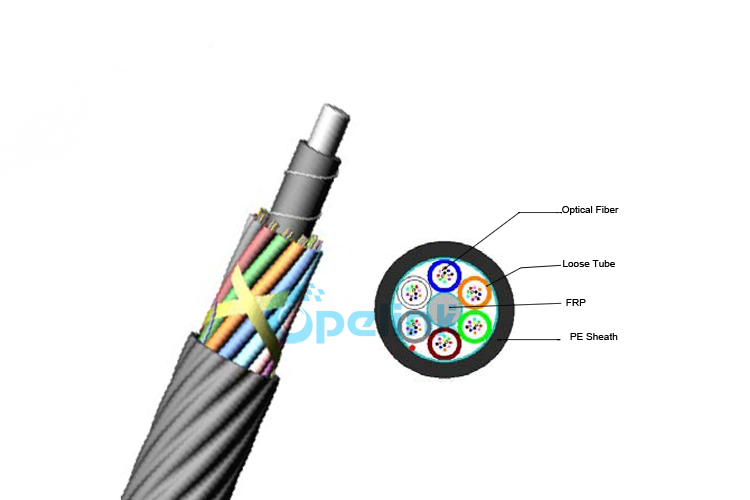
The compact loose-tube structure with SZ stranding provides high fiber density in a small diameter (5-12 mm depending on core count), while the dry water-blocking design eliminates gel mess for clean, fast splicing. The HDPE outer sheath is optimized for low friction coefficient, enhancing blowing performance in both straight and curved microduct routes.
Key Features
1.High fiber density: 12-144 cores in 5-12 mm diameter -- fits standard microducts (5/3.5mm to 12/10mm)
2.Long blowing distance: up to 2,000 m per blow at 50-150 m/min installation speed (15 bar pressure)
3.Dry core design: water-blocking yarn replaces gel -- clean splicing, no cleanup required
4.Low-friction HDPE sheath: optimized surface for maximum blowing distance in microducts
5.SZ-stranded loose tubes: uniform fiber length balance, stable performance across temperature range
6.Bend-insensitive option: G.657A2 fiber available for tight bend radius in FTTH drop applications
7.Ripcord access: easy sheath removal without damaging loose tubes -- saves 30% prep time
8.20-year design lifetime: UV-resistant, operating temperature -40C to +70C
Application Scenarios
1. FTTH / FTTx Drop and Distribution
Primary application. Air blown cables enable fiber-to-the-home deployment without trenching -- microducts are pre-installed during civil works, and fiber is blown in later when subscriber demand materializes. This 'pay-as-you-grow' model reduces upfront CAPEX by 40-60% compared to pre-cabled ducts.
Recommended: 12-48 core G.657A2 for drop, 48-96 core G.652D for distribution. Microduct sizes: 8/5mm for drop, 12/8mm for distribution.
2. Metro and Campus Networks
Air blown cables are ideal for metro feeder rings and campus backbones where future expansion is expected. New fiber can be blown into existing microducts without excavation -- a critical advantage for university campuses, business parks, and industrial zones where ground disruption must be minimized.
Recommended: 96-144 core G.652D. Microduct: 14/10mm or 16/12mm. Plan 30% spare duct capacity for future expansion.
3. Data Center Interconnect (DCI)
Between data center buildings or to nearby carrier hotels. Air blown cables enable rapid capacity upgrades -- new 144-core cables can be blown into spare microducts in hours rather than the days required for traditional cable pulling. The dry core design ensures clean splicing in data center environments where contamination is critical.
Recommended: 144 core G.652D, 16/12mm microduct. Consider OM3/OM4 multimode for short-reach DCI.
4. 5G Small Cell Backhaul
Air blown micro cables are increasingly used for 5G small cell fronthaul/backhaul in dense urban areas. Microducts can be installed in existing infrastructure (sewer pipes, utility poles, micro-trenches), with fiber blown in on demand as small cells are activated. The small diameter (5-7mm for 12-24 core) fits congested urban ducts where traditional cables cannot be installed.
Recommended: 12-24 core G.652D, 8/5mm microduct. Plan for CPRI/eCPRI bandwidth requirements.
5. Rural Broadband (FTTC/FTTB)
For fiber-to-the-cabinet or fiber-to-the-building in rural areas, air blown cables offer a cost-effective alternative to direct-buried cables. Microducts can be plowed in at shallow depth (200-300mm) using micro-trenching, with fiber blown in afterward. This reduces both installation cost and environmental impact.
Recommended: 48-72 core G.652D for cabinet feed, 12 core G.657A2 for building drop.
Air Blown vs Traditional Cable: Comparison
| Criterion |
Air Blown (GCYFY) |
Traditional Direct Buried |
| Installation method |
Compressed air jetting into microduct |
Cable pulling or direct burial |
| Installation speed |
50-150 m/min |
10-30 m/min |
| Max. install distance |
Up to 2,000 m per blow |
500-1,000 m per pull |
| Future expansion |
Blow new cable into spare microduct |
Re-trench or overlay new duct |
| Upfront CAPEX |
Lower (microduct + cable on demand) |
Higher (full cable + duct upfront) |
| Total cost (10-year) |
30-50% lower for staged builds |
Lower for single-build projects |
| Cable diameter |
5-12 mm (compact) |
10-25 mm (larger, armored) |
| Environmental impact |
Minimal (microduct pre-installed) |
Higher (trenching for each upgrade) |
| Fiber upgrade |
Hours (blow in new fiber) |
Days-weeks (trench + pull) |
| Best for |
FTTH, metro, campus, 5G, staged builds |
Long-haul, direct buried, single-build |
Installation Guidelines
Pre-Installation Checklist
1.Verify microduct inner diameter matches cable OD (fill ratio <60%)
2.Check microduct integrity: blow a test piston through the route before cable installation
3.Ensure microduct ends are sealed -- water or debris in the duct will block blowing
4.Confirm air compressor capacity: 15 bar pressure, 0.5-0.93 m3/min flow rate
5.Install air cooler at compressor discharge -- target air temperature <30C at duct inlet
6.Verify route map: count bends, measure total route length, estimate achievable distance
Blowing Procedure
1.Connect blowing machine to microduct entry point
2.Feed cable into blowing machine -- ensure straight feed, no kinks
3.Start air flow at low pressure (5 bar), gradually increase to 10-15 bar
4.Monitor blowing speed: 50-150 m/min is normal; sudden speed drop indicates obstruction
5.For routes >1,000 m: use mid-route assist (intermediate blowing machine at midpoint)
6.After installation: seal both microduct ends, leave 5m service loop at each end
7.Test installed fiber: OTDR trace from both ends, verify attenuation <0.38 dB/km after cabling
Common Installation Issues and Solutions
| Issue |
Cause |
Solution |
| Cable jams mid-route |
Excessive bends or high fill ratio |
Reduce fill ratio, add mid-route assist |
| Short blowing distance |
Wet or warm air increases friction |
Use air cooler and dryer |
| Cable won't start |
Debris in microduct entry |
Clean entry, blow test piston first |
| Speed fluctuation |
Variable duct friction or temperature |
Stabilize air temperature, check for kinks |
| Fiber attenuation increase post-install |
Excessive bending during blow |
Check bend radius, verify with OTDR |
Standards & Compliance
| Standard |
Description |
Status |
| ITU-T G.652D |
Single-mode fiber characteristics |
Compliant |
| ITU-T G.657A2 |
Bend-insensitive single-mode fiber |
Available option |
| IEC 60794-5-10 |
Microduct optical cable requirements |
Compliant |
| IEC 60794-1-21 |
Mechanical test methods |
Compliant |
| Telcordia GR-20 |
Optical fiber cable reliability |
Compliant |
| ISO 9001:2015 |
Quality management system |
Certified |
| RoHS |
Restriction of hazardous substances |
Compliant |
| CE |
European conformity marking |
Certified |
Available Configurations
| Core Count |
Fiber Type |
Cable OD (mm) |
Microduct (mm) |
MOQ |
Lead Time |
| 12 |
G.652D / G.657A2 |
5.0 |
8/5 |
2 km |
7-10 days |
| 24 |
G.652D / G.657A2 |
5.5 |
8/5 or 10/6 |
2 km |
7-10 days |
| 48 |
G.652D / G.657A2 |
7.0 |
12/8 |
2 km |
7-10 days |
| 72 |
G.652D |
8.0 |
12/8 or 14/10 |
2 km |
10-15 days |
| 96 |
G.652D |
9.0 |
14/10 |
2 km |
10-15 days |
| 144 |
G.652D |
11.0 |
16/12 |
2 km |
15-20 days |
Custom configurations available: non-standard core counts, hybrid single-mode + multimode, armored variants for rodent protection, and custom jacket colors. Contact sales@opelink.com for OEM/ODM pricing.
Why Choose Opelink for Air Blown Fiber Cable
1.Factory-direct pricing -- no distributor markup, 20-40% cost advantage
2.100% per-fiber OTDR testing on every drum -- zero-defect shipment guarantee
3.OEM/ODM capabilities -- custom core counts, fiber types, jacket colors, printing
4.Global shipping from Shenzhen -- DHL/FedEx for samples, sea freight for bulk
5.Technical support: installation guidance, microduct selection, blowing parameter optimization
6.20-year design lifetime with full material traceability
Multilingual sales team (English, Russian, Spanish, Portuguese) for global customers
Frequently Asked Questions
Q1: What is the maximum blowing distance for this cable?
Up to 2,000 meters for 12-24 core configurations in straight microducts with optimal conditions (15 bar dry, cooled air). For 144 core, the typical maximum is 1,000 meters. Real-world distances of 1,000-1,500 m are achievable with moderate route bends. Use mid-route assist (intermediate blowing machine) for routes exceeding 1,000 m.
Key Takeaway: 12-24 core = up to 2,000 m; 144 core = up to 1,000 m. Plan for 70% of theoretical max in real conditions.
Q2: Can I install this cable by pulling instead of blowing?
Yes, but it is not recommended. Air blown cables have lower tensile strength (600N installation) compared to direct-buried cables (1,500-3,000N). Pulling risks exceeding the tensile limit and damaging the loose tubes. If pulling is unavoidable, use a cable stocking lubricant and keep pulling tension below 400N.
Key Takeaway: This cable is designed for air blowing. For pull-in installation, use a GYTA or GYTS cable instead.
Q3: What microduct size do I need for 144 cores?
144-core cable has 11.0 mm outer diameter. Use a microduct with minimum 12 mm inner diameter (e.g., 16/12mm). The fill ratio is (11/12)^2 = 84%, which is above the 60% recommendation -- consider using 20/14mm microduct for better blowing performance. For 96-core (9.0mm OD), 14/10mm microduct gives a comfortable 81% fill ratio.
Key Takeaway: 144 core -> 16/12mm microduct (minimum) or 20/14mm (recommended). Keep fill ratio below 60% for best results.
Q4: What is the difference between G.652D and G.657A2 fiber in this cable?
G.652D is standard single-mode fiber with a bend radius limit of 30mm. G.657A2 is bend-insensitive fiber that tolerates bend radii down to 7.5mm with minimal loss increase (<0.1 dB per turn at 10mm radius). For FTTH drop applications with tight bends in subscriber premises, G.657A2 is strongly recommended. For straight metro/backbone routes, G.652D is sufficient and slightly cheaper.
Key Takeaway: G.657A2 for FTTH drop with tight bends; G.652D for metro/backbone with gentle bends.
Q5: How does the dry core design compare to gel-filled cables?
Traditional gel-filled cables use thixotropic gel in loose tubes for water blocking. The gel is messy, slows splicing (requires cleaning), and can drip at high temperatures. Opelink's dry core design uses water-swellable yarn and powder -- providing equivalent water protection without gel. Benefits: 30% faster splicing, no cleanup required, no gel drip in high-temperature installations, and easier cable access via ripcord.
Key Takeaway: Dry core = faster splicing, cleaner installation, equivalent water protection. No gel mess.
Q6: What is the lead time and MOQ for this cable?
MOQ is 2 km per configuration. Lead time: 7-10 days for 12-48 core standard configurations, 10-15 days for 72-96 core, and 15-20 days for 144 core. Custom configurations (non-standard core counts, hybrid fiber types, armored variants) require 20-30 days. Sample lengths (100-500m) are available for testing -- contact sales@opelink.com.
Key Takeaway: 2 km MOQ, 7-20 day lead time depending on core count. Samples available on request.
Q7: Can this cable be used for indoor installations?
The standard HDPE sheath is rated for outdoor use (UV-resistant, -40C to +70C). For indoor installations (building risers, data center trays), a LSZH (Low Smoke Zero Halogen) sheath variant is available on request. LSZH emits no toxic halogens and minimal smoke in fire conditions, complying with IEC 60332-1 and IEC 60754 standards for indoor building codes.
Key Takeaway: Standard = outdoor HDPE. For indoor, request LSZH sheath variant.
Q8: How do I order and what certifications come with the cable?
Order via inquiry on this page or email sales@opelink.com. Each cable drum ships with: (1) OTDR test report per fiber; (2) attenuation test data at 1310/1550 nm; (3) geometric measurement report; (4) certificate of compliance (IEC 60794-5-10, ITU-T G.652D); (5) ISO 9001 quality certificate; (6) RoHS declaration. Third-party certification (SGS, TUV, BV) available on request for project-specific requirements.